| |
|
Scalextric Sport
Race Start Controller
Kit484K Supplemental page
|
|
Overview
The original Race Start Controller
project includes a PCB layout for those that wanted to build it
themselves. However the PCB has never been available to buy from Picprojects. In 2010 I designed a new multifunction PCB, and the
original Race Start Controller has been modified slightly to work with
this PCB. The hardware design is essentially the same, the
firmware functionally unchanged, the only modifications to the code
being the I/O since different pins are used to accommodate the design on
the PCB480. You can read more about the PCB480 design
here can read more about the PCB480 design
here
This page provides construction details
for the new PCB and provides information on specific differences. It
connects to the Scalextric throttles in exactly the same way as the
original version and therefore rather than duplicate the information
here you should refer to them main project page for assembly and
connections to your slot car setup. (back to main
page)
You can buy a self-assembly kit of
parts from the Picprojects eShop
Schematic
This schematic is for the version of
the Race Start Controller assembled using PCB480 and sold as Picprojects
kit #484K.
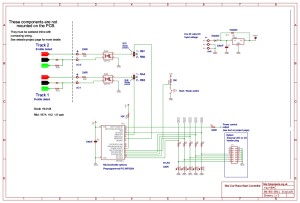
Download schematic PDF
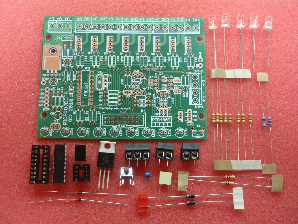
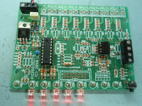
Construction
Construction details are shown below.
You can buy the PCB only or a kit of parts for this project from the
eShop. The kit #484K contains all the components required
to assemble the complete board as shown in the photo guide below,
including a pre-programmed PIC microcontroller.
Click on the photos below for 1024x768 version
|
Step 1 |
Step 2 |
Step 3 |
|
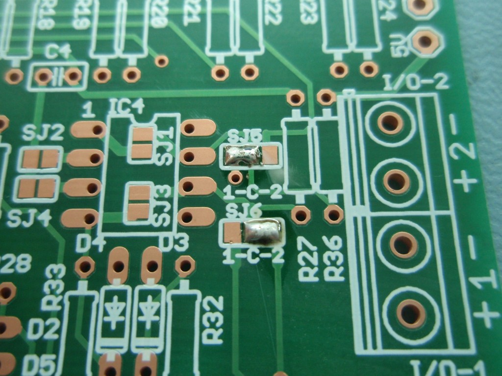
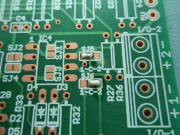
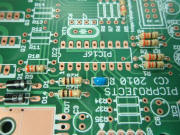
Step 1. Use a blob of
solder to bridge the two solder jumpers as shown. Be sure to
bridge only one half of each jumper.
Step 2. Install the
resistor identifying them using the coloured bands. It
doesn't matter which way round the resistors are fitted, the
coloured bands show the value not the orientation.
 brown, black, orange, gold - 10K
(R25, R26)
brown, black, orange, gold - 10K
(R25, R26)
 orange, orange, brown, gold - 330R (R1,R2,R3,R4,R5,R9,R32,R33)
Step 3. Install the
two 1N4003 diodes. Make sure to fit them with the silver band at the
end shown. (this matches the PCB overlay)
|
Step 4 |
Step 5 |
Step 6 |
|
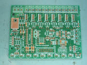
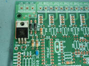
Step 4. Install the 100nF
capacitor C2. Will usually have the number 104 on the body (colour
of part may vary) Step 5.
Fit the 7805 voltage regulator IC
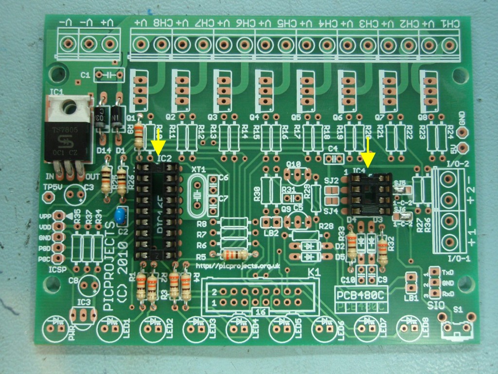
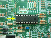
Step 6. Install the two IC
sockets. Note they are indented at one end. Fit the
socket so the indent is at the end arrowed.
|
Step 7 |
Step 8 |
Step 9 |
|
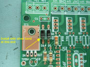
Step 7. Install the 330nF
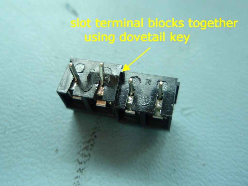
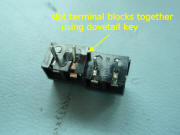
capacitor C1 Step 8.
Fit the two 2-way terminal blocks together using the dovetail key.
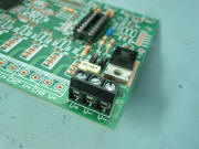
Step 9. Install the switch
and terminal blocks.
 If you are using an alternative switch mounted away from the PCB you
may want to omit the switch and solder wires to the switch position
on the PCB. In this case connect to the two smaller holes
within the switch outline of the component overlay.
If you are using an alternative switch mounted away from the PCB you
may want to omit the switch and solder wires to the switch position
on the PCB. In this case connect to the two smaller holes
within the switch outline of the component overlay.
|
Step 10 |
Step 11 |
Step 12 |
|
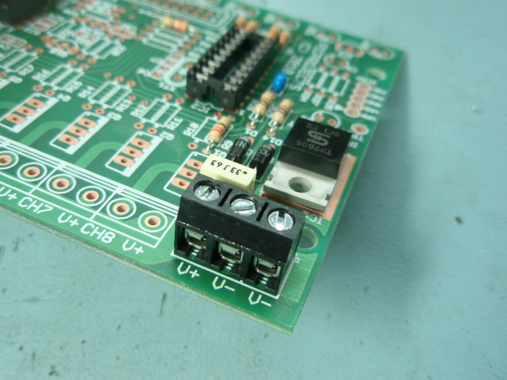
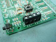
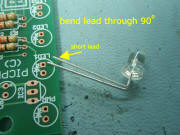
Step 10. Install the
3-way terminal block Step
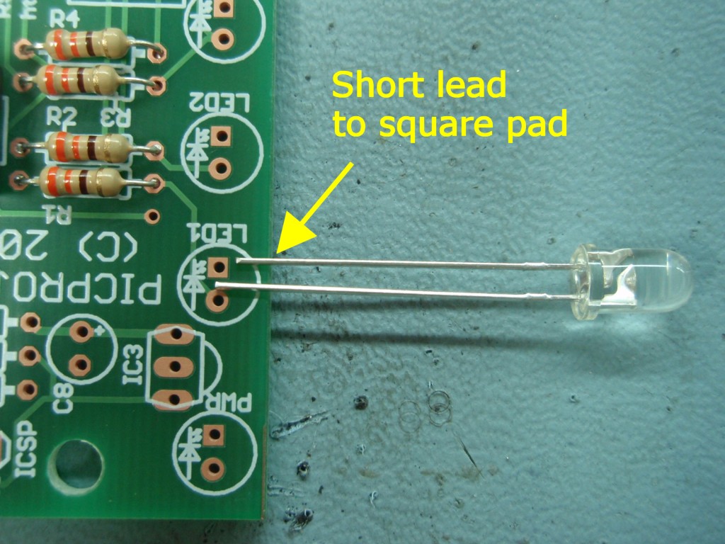
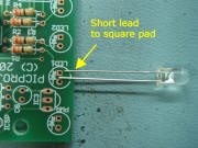
11. Install the five LEDs into positions LED1 to LED5.
Make sure to identify the short lead and fit it into the hole with
the square pad as shown.
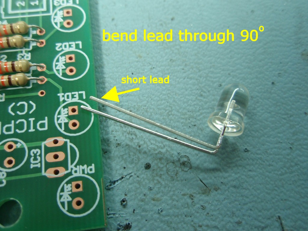
Step 12. You may want to
bend the leads through 90o in which case make sure to bend it so the
short lead will still fit into the hole with the square pad.
|
Step 13 |
Step 14 |
Step 15 |
|
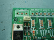
Step 13. Before
proceeding this is a good point to check the PCB for bad solder
joints, solder splashes or bridges and any component lead off-cuts
that may be stuck to the PCB. Having done this apply power to
the board at the 3-way terminal block and use a multimeter to
measure the voltage at the 5 volt test point. (see photo) It should
measure between 4.75 and 5.25 volts, if it doesn't investigate the
cause before continuing.
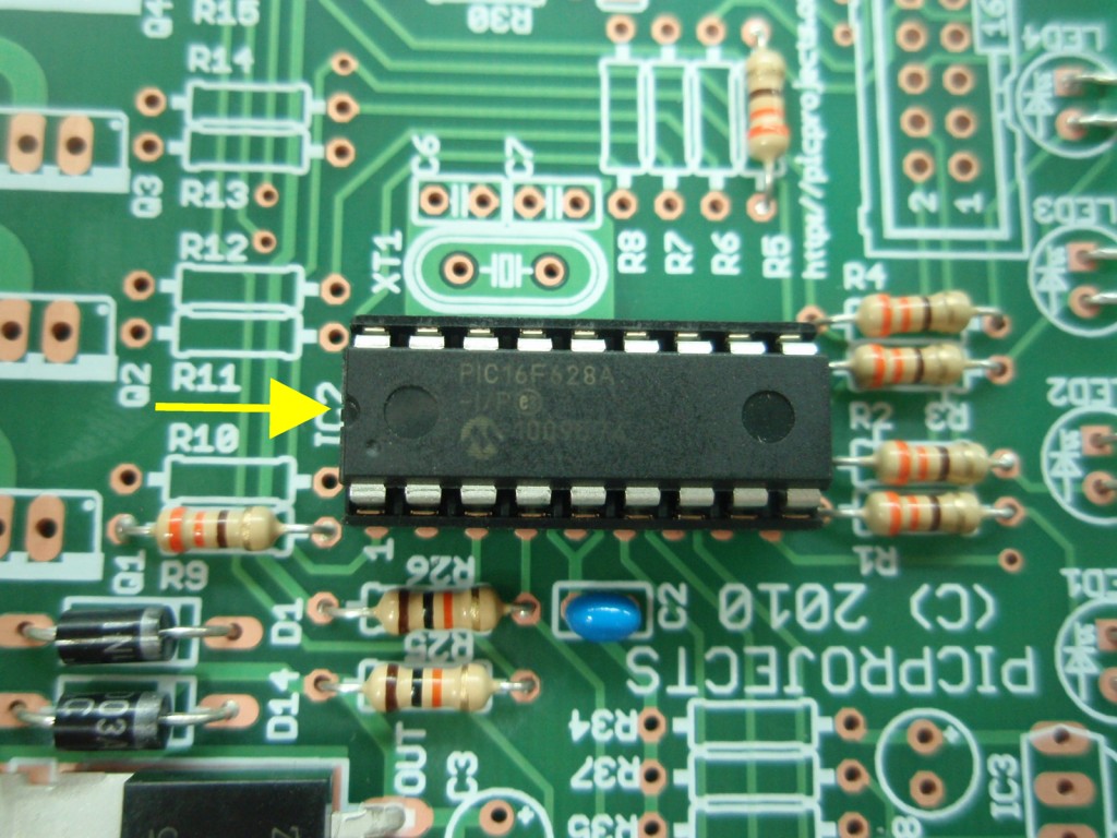
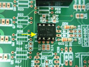
Step 14 / 15. Disconnect the power to the PCB.
Next install the PIC16F628A and CNY74 opto-isolator into their
respective sockets. Make sure to fit the IC's with the indent
in the IC package at the end shown arrowed
|
Step 16 |

Step 17 |

Step 18 |
|
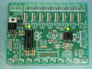
Step 16. With
all the parts fitted, reconnect the power to the PCB through the
3-way terminal block.
You can now test the
board by pressing S1. With no external connections from the
throttles it appears to the firmware that the throttles are closed
so the board with go through a normal start sequence each time S1 is
pressed. If you press and hold S1 it will enter the setup mode
as described on the main page.
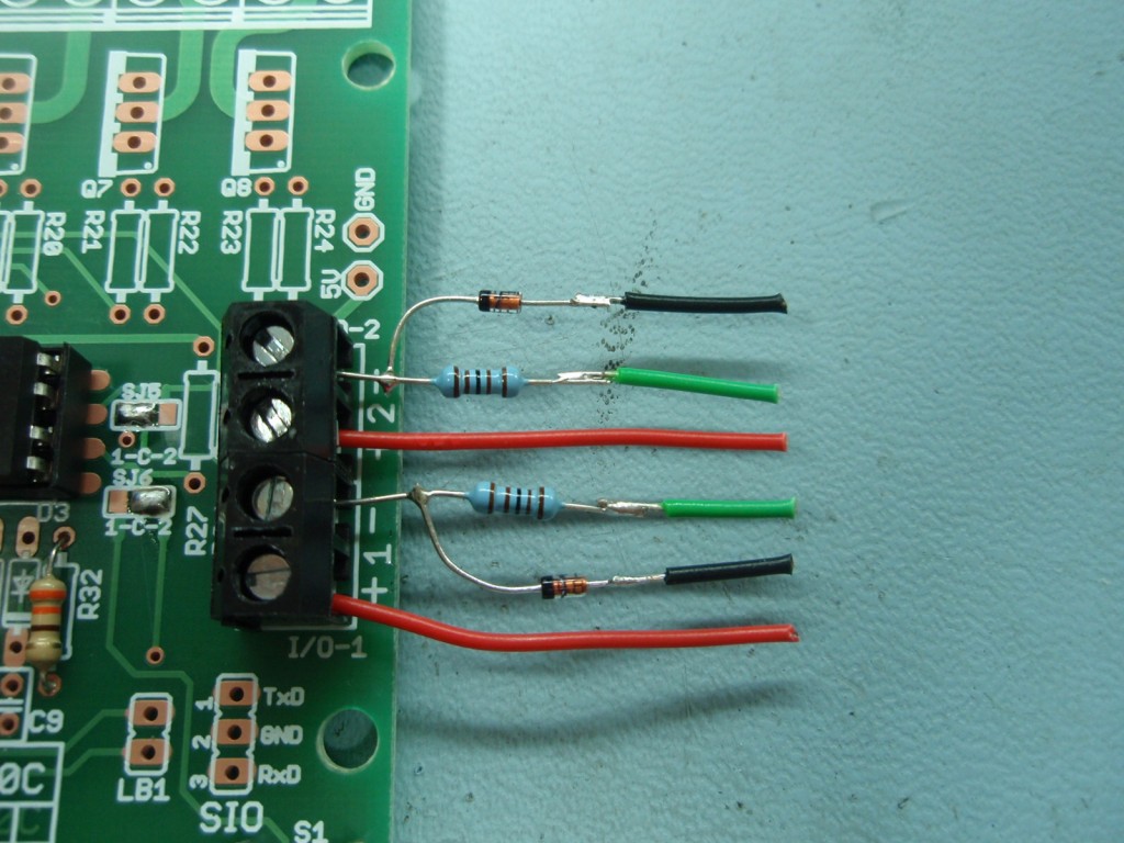
Step 17. Since
the PCB used is a multifunction board, the diode and resistor
connecting to the throttles are not accommodated on the PCB.
The photo shows how they should connect between the throttles and the
terminal blocks. Wire tail colours correspond to the diagrams
on the main project page
This is done to
provide a clear illustration of the wiring. It is not
recommended to assemble the resistor and diode without suitable
insulating sleeving. (see Important notes section below)
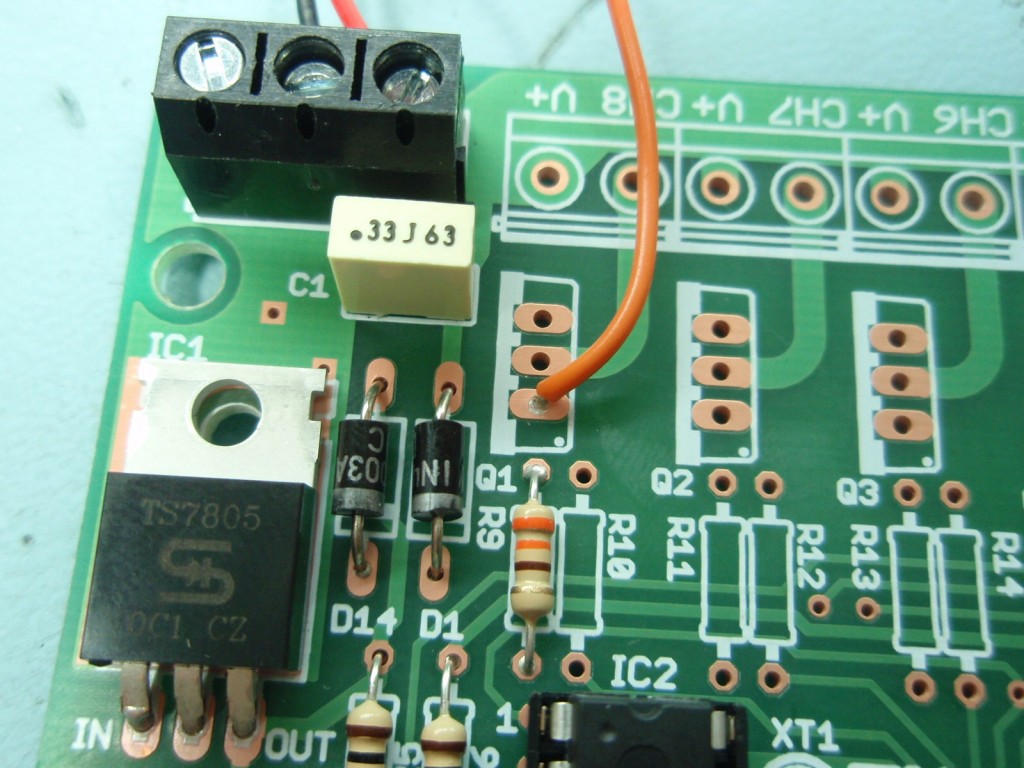
Step 18. The
original start controller has a connection to operate a 'power
control' output. This output is also available and connects to
the PCB at the point shown by the Orange wire in this photo.
If you're not using the power control output you can ignore this
step.
Important notes
These notes cover
some details important to getting the project working correctly.
Please read
Connecting
power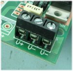
The power supply to the board connects via the 3-way
terminal block. The PCB is marked V+ and V- indicating the
positive and negative power input. There are two V- connections,
either can be used. The board has reverse
polarity protection so if you accidentally connect it the wrong
way the board shouldn't be damaged.
Connecting LEDs
using the option header K1
Rather than
mounting the five LEDs on the PCB they can be connected via
cables using the optional header. You can buy a 16-way IDC
header socket, plug and cable from the Picprojects eShop under
the 'Components - Connector/Cables' product section
If you use the header to connect the LEDs do not fit LEDs to the
PCB (it's either/or not both)
Power supply
requirements
This version of
the controller needs a smoothed DC power input. The
Scalextric Power Supply supplied with the track does not have an
output smoothing capacitor so isn't directly suitable for use
with this PCB.
If you are building this project in conjunction with the
power
supply project you can use the power from that. If you are
retaining the original Scalextrix Power Supply, this board will
need powering from a separate DC power supply. Since the
board has its own regulator on board any 9-18 volt DC power supply
that is rated for 150mA or greater will work.
Connecting the
throttles
Since the PCB used
is a multifuction board one resistor and diode in each throttle
channel have to be
mounted off the PCB. When I built the original projects I
replaced the 3.5mm jacks on the throttles with 3-pin XLR
plugs and sockets. If you are doing similar the back of
the socket would be a good place to fit the diode and resistor.
You can then run two wires back to the terminal block on the PCB
(with two throttles you will have two pairs of wires going back
to the PCB)
The schematic
diagram on this page uses the same red / black / green
identifiers for the connections to the throttles. You can
therefore refer directly to the main page for additional
information on connecting to the slot car throttles and track.
|
PIC
Firmware
The PIC supplied with the
kit #484K includes a pre-programmed PIC16F628A so you don't need to
download this code or program the PIC yourself. However, should
you need to reprogram the PIC for any reason you can download the
original code here.
The HEX file ready to
program into a 16F628A can be downloaded for free from
here
(right-click Save As).
(a 16F627A can also be used without any modification to the code or
hardware)
|
Description |
Filename |
Download link |
| HEX
file ready to program into the PIC |
480-scs-main.HEX, v1.0.0. 06/02/2011 |
 download
checksum 0xAFCD |
|