|
|
Scalextric Sport
Race Start Controller
with jump start detection
From
this page
|
|
Overview
I developed this after my nephews got a
Scalextric Sport slot car racing set for Christmas. The set included
a lap timer and counter but one thing that was missing was a way to start
a race. Having someone say "3-2-1-Go" wasn't really doing
the job, especially as it was easy to go just after "1"
and before "Go" This works in a similar way to the lights
used in F1 motor racing with five lights illuminating sequentially,
holding for a random time before all lights turn off to signal the race
start.
I put together a battery operated version
one afternoon between Christmas and New Year, it took about four hours
from concept to completed hardware in a box. [see
original] It worked quite well but we still had the issue of 'jump
starting' so I decided to develop things further.
I had four key requirements for the design.
- It should work with the standard
Scalextric power-base (part C8217), throttles and transformer pack.
- It had to be simple to use.
- Powered from the Scalextric power
supply, no extra transformers or batteries.
- Not require any alterations to the
Scalextric power-base, throttles or cars.
I know that there's a lot of computerised
solutions that will do all kinds of smart things out there, including
controlling the start of a race, but not everyone wants or needs that
level of complexity. The device described on this page is easy to
use, cheap to build and doesn't require any permanent modifications to the
original Scalextric setup, although it can be hard wired in to permanent
setup should you wish to do so.
Using the controller is very simple. To start a race simply press the start
button. The controller than waits for both hand throttles to be
released before starting the countdown. During the countdown the
LEDs illuminate at 1 second intervals until all five LEDs are on.
The start of race is signaled when the LEDs extinguish after a random
delay of between 0 and 3.5 seconds.
The start controller detects a jump start
by sensing the hand throttle; if it's operated during the countdown the
controller will either ignore it, display a Jump-Start condition on the
LEDs after the countdown completes, or abort the countdown and display
Jump-Start condition on the LEDs. This action is determined by the
operating mode which is user configured.
Operation
and modes
-
Mode 1 - Turn
track power off during start sequence, restore power at 'Go' signal.
-
Mode 2 -
Normal start countdown, no jump start detect.
-
Mode 3 - If
jump start detected during countdown, track power is cut, start
sequence aborts and jump start condition is displayed on LEDs..
-
Mode 4 - If
jump start detected during countdown, start sequence continues and
then one
second after 'Go' signal Jump start condition is displayed on the LEDs.
Graphical representation of the four
modes are shown in the PDF document here.
If the Controller is used on its own
without the PSU described here then modes 1
and 2 behave in the same way. Reference to the track power is also only
relevant when used with this PSU. The Controller still functions in
all other respects as described.
Start Race
To start a race countdown, press and
release the start button. LEDs 2 and 4 light if the controller has
detected an open throttle. Countdown commences when both throttles are
released.
Change Modes
To change modes, press and hold the start
button for 3 seconds. When the controller goes to mode change setup a
single LED will light indicating the current operating mode.
Repeatedly pressing the start button will cycle through the four modes.
When the desired mode is selected press and hold the start button for 3
seconds until the LED turns off.
Operating modes can be changed at anytime,
except when a start is in progress. The
mode is saved to non-volatile memory so the controller will start up in
the mode that was selected when it was last used.
Construction
Full details of the Race Start Controller
with schematics and PCB layouts are provided below. Click
on the images for full size view.
|

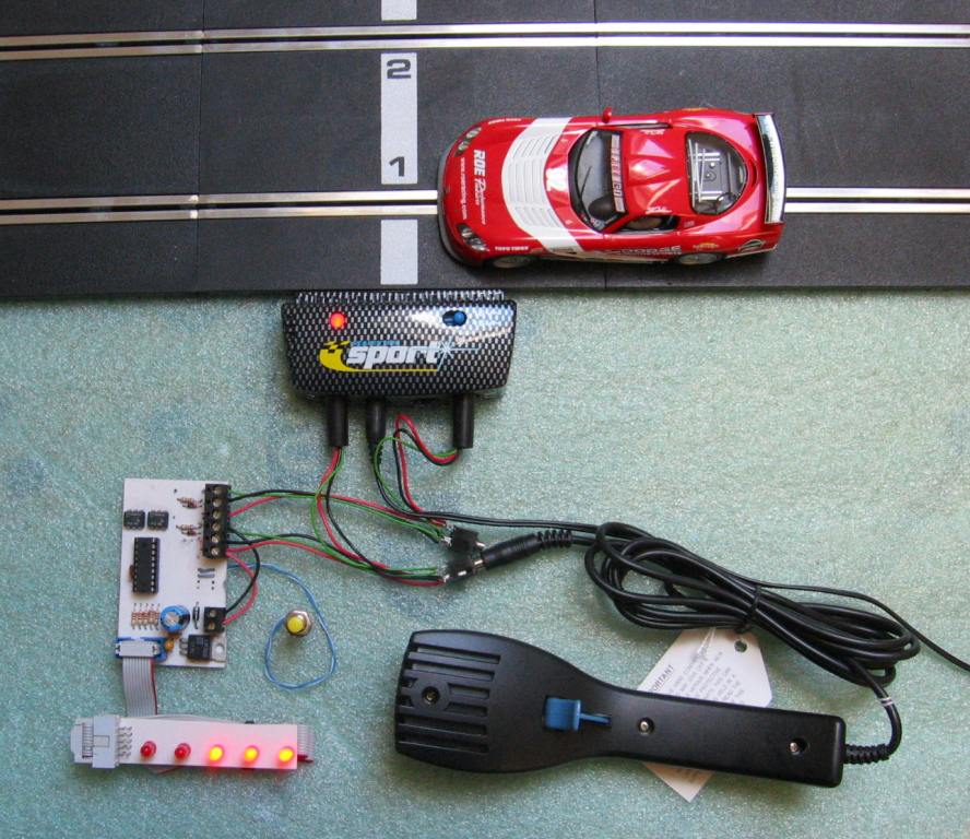
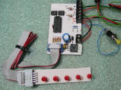
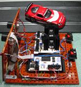
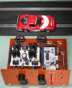
Photo of the start
controller connected to a standard Scalextric Sport powerbase and
throttle. |
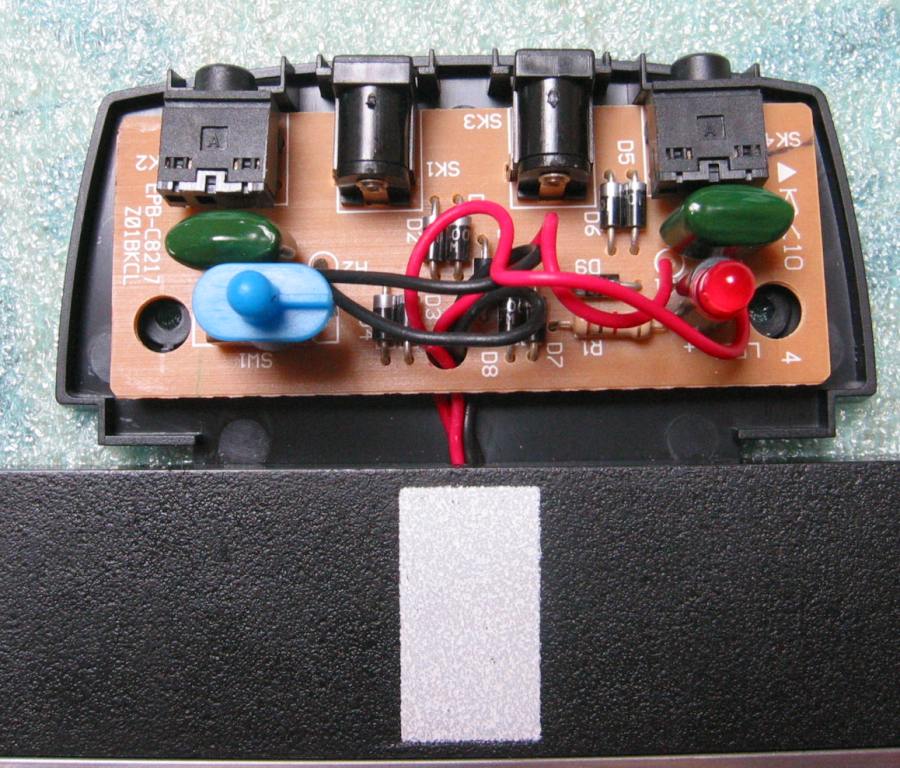
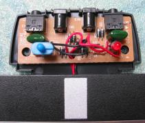
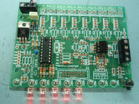
Close up of the start controller
PCB. I've used PCB mounted screw terminal blocks for the connections to the
throttle wiring, power and an IDC header for the LED board. There is no
reason why the wiring can't be made directly to the PCB saving the cost of the
connectors. |

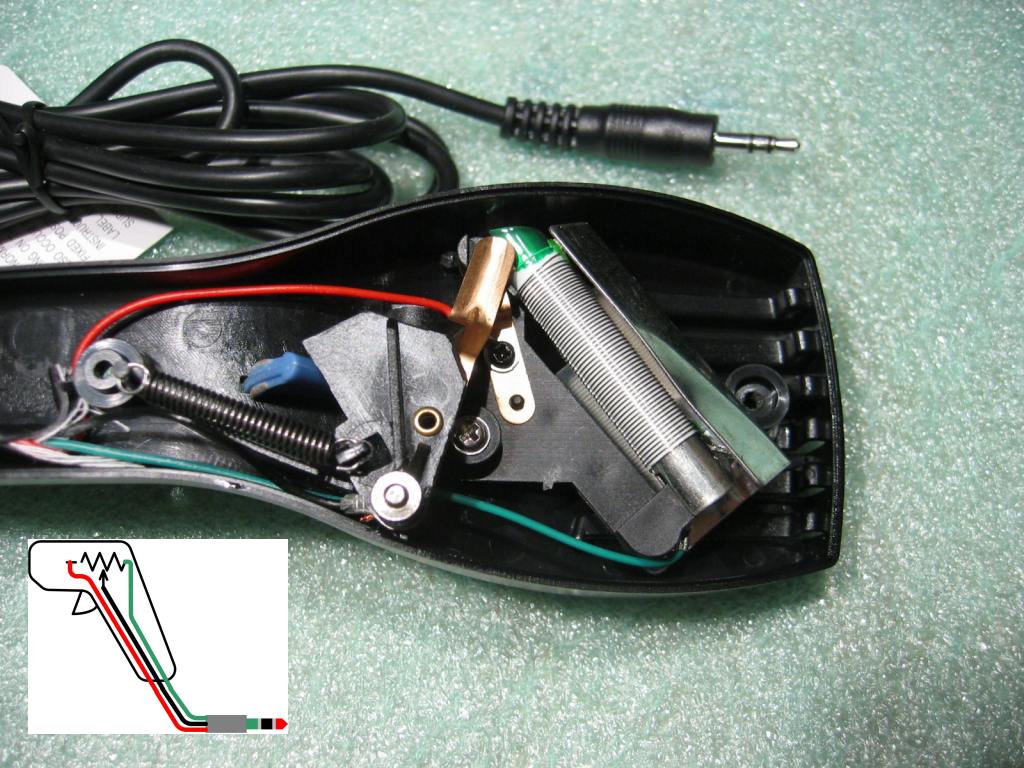
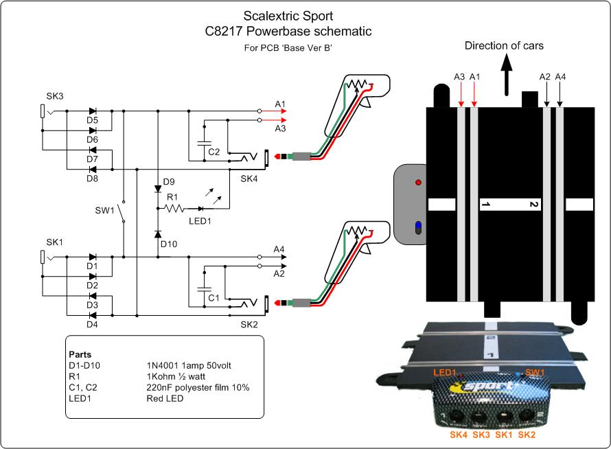
Inside a standard 45ohm Scalextric
Sport hand throttle. The inset diagram shows how the throttle is wired.
When the throttle is in the closed position (as shown in the photo) the wiper
(black wire) short circuits to the 'brake' contact (red wire). It is this feature that is
used to detect jump-starts. |
|
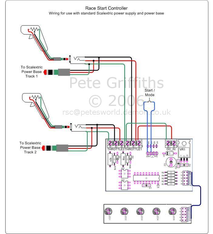
| The
wiring and circuit schematics show how to connect the Race Start
Controller to your Scalextric Sport powerbase track and hand throttles.
If you're building this I assume
you have some knowledge of electronics and circuit construction. The electronic side of the circuit
operation is fairly self explanatory.
|

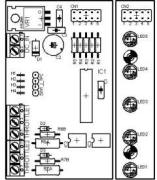
Wiring Schematic
click here for PDF version
|
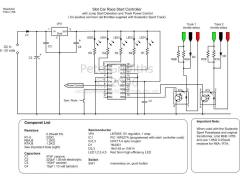
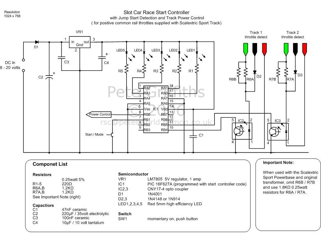
Race Start Controller Schematic
click here for PDF version
|
| A schematic
diagram of the internals of the Sport Powerbase track part
C8217.
You can see from this that
the power delivered to the car is unsmoothed DC. D1/C2 on the controller PCB isolate and smooth this
supply which is then fed into voltage regulator VR1 to get a 5
volt output for the controller. |
 |
 |
| |
PDF version |
|
A few facts, traps and other information
to be aware off during construction and testing.
-
As detailed
on the circuit schematic, you must use 1.8Kohm resistors for R6A and
R7A and omit R6B and R7B.
-
I recommend
powering up the circuit without the PIC installed and using a
voltmeter to check that you have something between 4.8 and 5.1 volts
between pins 5 and 14 of the IC socket. If not correct the
problem before inserting the PIC.
-
The
standard Scalextric Sport Power base transformer pack outputs 16V RMS
under full load. Without a load (that is when the cars are stationary)
the peak output can be almost 27 volts. Therefore the 220uF capacitor, C2 on the schematic, which is
shown rated at 35 volts should not be substituted for a 25 or 16 volt
alternative.
-
The jump
start detection works by sensing when the throttle wiper is contacting
the brake connection. Some throttles are more sensitive than others
where this is concerned. If the controller continually shows a
throttle open status when you press the start button, check that both
throttles are connecting the wiper to the brake contact in the
throttle.
-
Be careful
when wiring the 3.5mm jack plugs that the wires and connectors don't
short together when you slide the cover on. Ideally use some sleeving
over the soldered connections.
-
The wire
colours shown are those I've found in a number of Scalextric Sport
hand throttles and I've used those in the schematics for ease of
reference. I don't suppose they'll change it, but it's
always worth checking.
-
The
Scalextric Sport Powerbase allows either a single transformer to be
used or separate transformers for each track. The start
controller will work with either configuration without modification.
-
The start
controller circuit uses ~75mA with all five LEDs illuminated and under
5mA with all LEDs off. Each throttle sense opto-coupler will
draw around 10mA continually.
-
The
throttle sense circuit works by using the lower forward voltage drop
of a normal diode to 'by-pass' the LED in the opto-coupler when the
throttle wiper connects to the 'brake' terminal. This also means
that when no throttle is connected, it appears to the controller that
the throttle is closed so the circuit can be used with only one
throttle
-
The
throttle detect circuit works with a common positive brake
connection. The throttle wiper varies the negative supply to the
track. It's not how I would have designed it myself, but that's how
Scalextric have done it so that's what it has to work with and to be
fair it doesn't really make any difference.
-
When I got
into building this I bought another Powerbase track section and four
sets of hand throttles to pull apart, test and play about with.
The circuit has been used with my test track, the original track the
kids got for Christmas and with six different Scalextric hand
throttles. I've not had any problems, but if you do I'd be interested
to know more - drop me an email.
Testing
Once the circuit is constructed,
connect to the Powerbase as shown in the wiring schematic
above. It's not necessary to have any cars on the track while
you're testing the controller.
When power is first applied, the LEDs
illuminate in a sweeping pattern to indicate it has powered on okay.
- If you now hold open one of the
throttles and then press the start button you should see LEDs 2
and 4 illuminate.
- Release the throttle and LED 1
should light followed by LEDs 2 to 5 at 1 second
intervals.
- When all five LEDs are on they
will turn off after a random delay of 0 to 3.5 seconds.
- Repeat steps 1 to 3 with the
other hand throttle.
If it has worked as described, the
circuit is functioning correctly.
|
|
PCB Artwork
The Controller PCB and
LED PCB are done as one layout. You can either cut the artwork and
etch the boards separately or etch the board as one and cut the PCB
afterwards which is how I do it.
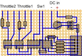
If you're not able to
make your own PCB here's a prototype pad board layout. You should be
able to work out from the schematic what the components are. The
layout is similar to the PCB and the connections at the edge are the
same as those on the PCB so the wiring schematics can still be
followed.
|
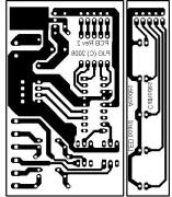
PCB Layout (PDF)
Component Overlay
(PDF)
|
|
Alternate
PCB and component kit for this project.
You can now buy a PCB and kit of parts
for this project. It uses an alternate PCB design to that
shown above.
An an additional project page has
been added with full construction details. The assembled board
can be substituted for the one shown on the main page here
See kit #484 supplemental project page |
 |
Parts
Listing
You can buy all the parts
needed to build this project from most component suppliers world
wide. In the UK you can get everything from Rapid Online and
I've included a parts list with their part numbers below.

-
All
Rapid parts/descriptions correct at 19-Sept-2008. You should
check part# and descriptions are correct when ordering in case
I've made a mistake transferring them onto this page.
-
The
resistors are sold by Rapid in packs of 100 and the ribbon cable is a 30M reel. You may find it
cheaper to buy some or all of the parts from other sources - I make no
recommendation.
-
You will also needs some short
lengths of wire for the interconnections between the PCB and the jack plug
and sockets. Rapid sell a pack of 11 colours x 2M lengths of stranded
equipment wire, Part # 01-0108
| Qty |
Part Number |
Description |
| 2 |
20-0125 |
3.5mm stereo jack |
| 2 |
20-0155 |
3.5mm stereo socket |
| 1 |
78-0040 |
Green push button switch |
| 1 |
47-3130 |
1N4001 diode |
| 2 |
47-3308 |
1N4148 diode |
| 1 |
47-3313 |
7805 5volt regulator |
| 2 |
58-0826 |
CNY17-4 opto-coupler |
| 5 |
55-0155 or 55-0117 |
5mm bright red LED
or standard red LED |
| 1 |
73-3384
(needs programming see
below ) |
Microchip PIC 16F627A |
| 5 (sold in packs of 100,
order Qty 1) |
62-0354 |
220 ohm 0.25 watt resistor |
| 2 (sold in packs of 100,
order Qty 1) |
62-0376 |
1.8K ohm 0.25 watt
resistor |
| 1 |
11-1022 |
10uF / 16volt Tantalum
Capacitor |
| 1 |
08-0237 |
47nF disc ceramic
capacitor |
| 1 |
08-0235 |
100nF disc ceramic
capacitor |
| 1 |
11-0355 |
220uF / 35v electrolytic
capacitor |
| 1 |
21-1810 |
2-way, 16A interlocking
terminal |
| 2 |
21-1812 |
3-way, 16A interlocking
terminal |
| 2 |
19-0500 |
10-way box header |
| 2 |
19-0300 |
10-way cable mount socket |
| 1 |
01-0167 |
10-way ribbon cable 30M
reel |
| 1 |
22-0165 |
18 pin DIL IC socket (for
16F627A) |
PIC
Firmware
The Microchip PIC 16F627A
requires programming with the firmware for the start controller.
The HEX file ready to
program into a 16F627A can be downloaded for free from
here
 (right-click Save As). (right-click Save As).
(a 16F628A can also be used without any modification to the code or
hardware)
 If you have problems programming the HEX file into the PIC make sure you
are using Vpp first programming mode. For PICkit2 programmers you
can find this option under Tools - Use VPP First Program Entry
If you have problems programming the HEX file into the PIC make sure you
are using Vpp first programming mode. For PICkit2 programmers you
can find this option under Tools - Use VPP First Program Entry
This code works with the
hardware design shown on this page only. For the code used with
the Race Start Controller kit #484 please see the
supplemental project page
Use
with other slot-car systems
Not having experience with
other makes of slot-cars I can only say it works with Scalextric, though I
expect it would work with other makes that use a three wire throttle.
If you want to use the circuit
with other throttle systems the following information will help.
The throttle detect works as
follows. The PIC port pins RB4 and RB5 detect throttle 1 and throttle
2 respectively. A high logic level on either pin signals to the PIC
firmware that the respective throttle trigger is released (closed) and a low
logic level signals the throttle is open (trigger moved). The
'weak internal pull-up' feature is enabled on the PIC so no external pull-up
resistors are needed on these inputs.
Resistors R6A and R7A set the
current through the LEDs in the opto-couplers. Ideally for a given
input voltage the peak LED current should not exceed 50mA and the average
current ought to be around 10-15mA. When the throttle triggers are
released the resistors are dropping Vin-0.6 volts, the drop across the
1N4148 diode. This is the highest dissipation condition and you need
to make sure that the power dissipation in the resistors does not exceeded
their maximum rating.
The PCB layout was
specifically designed to take two resistors in parallel which allows
standard 0.25 watt resistors to be used where the power dissipation in one
resistor alone would exceed 250mW.
You also need to consider that
with transformer packs like that supplied with the Scalextric the off-load
output voltage is higher than the voltage stated.
For example. With the 16
volt AC / 800mA transformer pack supplied with the Scalextrix I measured an
offload RMS output of 19 volts (peak 26.8 volts). Fully loaded the RMS
output of 16 volts has a peak of 22.5 volts.
Dual
Output PSU
You may have noticed on the
controller schematic a 'Power Control' signal from RB0 pin of the PIC.
I've also designed and built a dual output variable voltage power supply for
my Scalextric setup. This features a power shutdown input which, when used
with the race controller described above, shuts off the power to the track
when a jump start is detected. It also has a 'launch control' start mode
where power is cut to the track during the start countdown and then restored
when the LEDs go out.
See
full PSU project here
Development rig
|