This project was inspired from a
post on the Picprojects forum where a member had adapted the RGB Moodlight project
for use as a strobe and beacon for a model aircraft.
I thought this would be of
interest to others so I've put this page together with
schematic, examples and free code download. You can also
buy a PIC pre-programmed with the firmware from the Picprojects
e-Shop
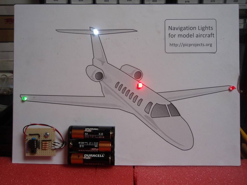
The sequence
data has been custom written to produce the beacon and strobe
light effects found on aircraft and boats.
The design has been kept as
simple as possible to keep the size small and therefore easy to
build into a model. The circuit has very low power
consumption and can be powered from Alkaline or rechargeable
batteries.
It is not necessary to use all
the outputs, for example the beacon output is also very
effective for use in a model Lighthouse.
For those with access to a PIC
programmer the source code is available to allow you to
customise the sequences and program the PIC with your own
effects.
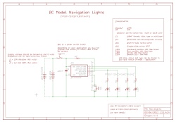
The circuit use a PIC
microcontroller, IC1, to drive LEDs with a pulse width modulated
(PWM) signal that allows the brightness of each LED to be
controlled and faded.
There are a number of sequences
programmed into the PIC and these can be selected by pressing
the sequence select switch SW1. Each time the switch is
pressed the next sequence is selected, when the last sequence
has been reached it returns to the first. The
selected sequence is saved to non-volatile EEPROM about 10
seconds after the switch is pressed. On power-up the last
saved sequence is used.
There are two versions of this
project and two versions of the firmware which can be downloaded
at the bottom of the page.
Basic version: all
outputs operate continually while powered on.
Servo Controlled Version:
Outputs are activated under control of an RC servo pulse input.
The outputs still perform the same stobe/beacon/position lights
when active but can be turned off under control of the servo
signal
The servo pulse is monitored on
the GPIO4 input of the PIC. The signal on the PIC input
needs to be active low so the NPN transistor Q1, is used to
invert the normal servo pulse signal.
When the servo pulse is
between:
1ms - 1.25ms all outputs
are off
1.25ms - 1.5ms output
GPIO2 is active
1.5ms - 1.75ms outputs
GPIO2 and GPIO1 are active
1.75ms - 2ms GPIO2, GPIO1
and GPIO0 are active
Important: The Servo
controlled version will not operate without a servo control
signal present
Servo version demo video
The video shows a small test
board with two PIC microcontrollers on it. The one on the
left is programmed to generate servo pulses, cycling through
four pulse widths. These a fed to the Servo controlled RC
Navigations Lights firmware which is running on the second PIC
microcontroller (right). Although you wouldn't normally
connect a Servo to the receiver output controlling the PIC, just
to demonstrate that it is a servo control pulse I have also
connected a small RC servo motor. The 'scope is showing
the servo control pulse.
Outputs
For the Model Navigation Lights
project the function of the outputs is predefined.
GPIO0 (pin 7) operates as
a anti-collision beacon simulating a rotating light.
GPIO1 (pin 6) operates as
a strobe
GPIO2 (pin 5) is driven
with a constant 30% duty cycle signal for navigation lights
LEDs on GPIO2 are driven with a
30% duty cycle which reduces overall battery drain and if you
want to dig into the source code and alter the sequence data (in
the RCnavLightsData.inc file) you can modify the duty
cycle to
adjust the brightness. You could can also leave this output unused and just wire
the LEDs directly across the battery (not forgetting the current
limit resistors!)
The schematic shows one LED
attached to each of the GPIO0 and GPIO1 outputs. You can
if required add a second LED to these outputs by using a second resistor and LED
as we have done with the navigation LEDs connected to GPIO2.
The resistor values shown on
the schematic for the LEDs are 270 ohms. This will work
for almost all types of 3/5/10mm LEDs. To increase the LED
current and brightness (at the expense of battery life) you can
use a lower value resistor but don't go below 150 ohms.
LEDs
For the navigation lights shown
we have used red, green and white LEDs but you can use any
colour LED you want to suit your project. The PIC
can directly drive (via a current limit resistor) LEDs up to
25mA per output. Most small 3/5/10mm LEDs will work.
If you want to drive higher power LEDs you can use the firmware
for this project with the
Power MOSFET RGB LED Driver project
Capacitor C1,C2 and Resistor R5
Capacitor C1 provides power
supply decoupling. It is important this is fitted as close to the power supply pins of IC1 as possible.
Ceramic capacitors come in either disc or multilayer type -
multilayer ones are generally smaller but either type will work.
Capacitor C2 provides peak
current reservoir and helps extend useful battery life.
The exact value isn't critical, 47uf up to 150uF will be okay.
A Tantalum rather than Electrolytic capacitor can also be used.
Make sure to connect with the correct polarity whichever type
you use.
Resistor R5 is used to pull up
the MCLR reset input on the Microcontroller. If it isn't
fitted the circuit will operate erratically or not at all.
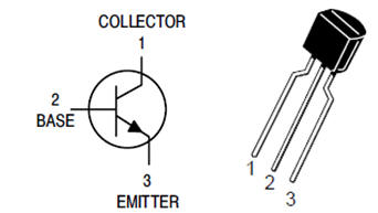
Transistor Q1 and Resistor
R6
Only used with the servo
controlled version. Q1 inverts the normal active high
servo pulse which is required by the PIC microcontroller.
R6 is a 1K0, 0.25w resistor. Pinout for transistor Q1, a
BC547 is shown right.
BC546/7/8/9 all use this pinout
and can be substituted for the BC547. Use whichever is cheapest
or easiest to obtain.
SW1 Switch
Is used to select the sequence
effects. Any small push-to-make type switch should work
here.
Since the last selected
sequence is saved, if you are trying to keep the circuit as
small as possible you can make a temporary switch connection to
set the sequence you require, them remove it before building it
in your model.
SW2 Power Switch
Depending on how you use this
project you may be powering it from some other power source that
already has a power switch. If not, you will probably want
to fit a SPST (single-pole, single thow) slide or toggle switch
to allow the circuit to be switched on and off.
Power Supply
The circuit as shown in the
schematic draws an average current of around 7mA operating from
a 4.5 volt supply.
It can be powered from three 1.5
volt alkaline batteries or four 1.2 volt NiMH rechargeable
batteries. The PIC microcontroller will operate
with a supply voltage from 3 volts to 5 volts but high
brightness LEDs will need a minimum supply voltage of 4 volts to
operate effectively. The power supply must not
exceed 5 volts otherwise the PIC microcontroller may be
permanently damaged.
There is no reverse polarity
protection in the circuit so it is important you connect the
battery / power supply the correct way round. If you
reverse the positive/negative terminals of the battery it will
damage the PIC microcontroller.
You can buy all the parts
needed to build this project from most component suppliers world
wide. In the UK you can get everything from Rapid Online and
I've included a parts list with their part numbers below.
All
Rapid parts/descriptions correct at 02 June 2012. You should
check part# and descriptions are correct when ordering in case
I've made a mistake transferring them onto this page.
Kingbright L-7113SGC
5mm Super Bright Green LED 250mcd
55-0135
LED2**
Kingbright L-7113RC-F
5mm Super Bright Red LED 4500mcd
72-8982
LED3**
Ospw5111a-st 5mm White
LED 10000mcd
55-1886
LED4**
Kingbright L-7113RC-F
5mm Super Bright Red LED 4500mcd
72-8982
socket for IC1
8 Pin 0.3in Turned Pin
Socket
22-1720
SW1
Tactile Switch 6x6mm
Height 4.3mm
78-0620
SW2***
Miniature vertical
slide switch
76-0310
Parts List Notes
All the resistors are
supplied in packs of 100
*
PIC12F629
will need to be programmed with the HEX file available to
download at the bottom of this web page.
** Choose LEDs to suit your specific application for this
project.
*** Suggested switch only, if required use any switch
that integrates into your model / application.
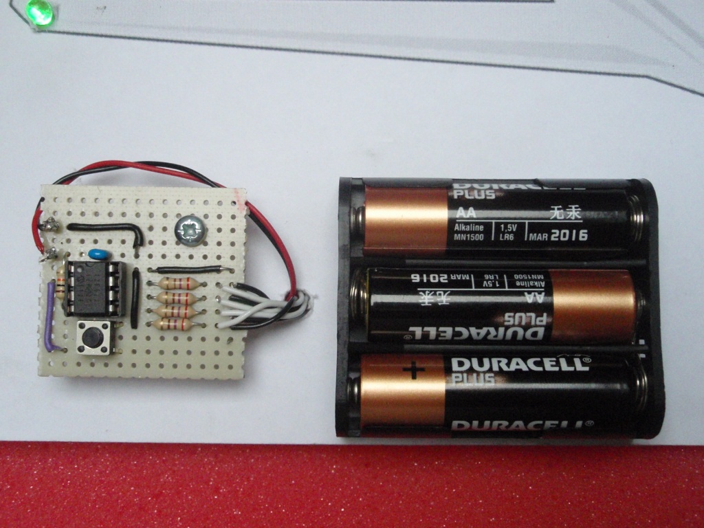
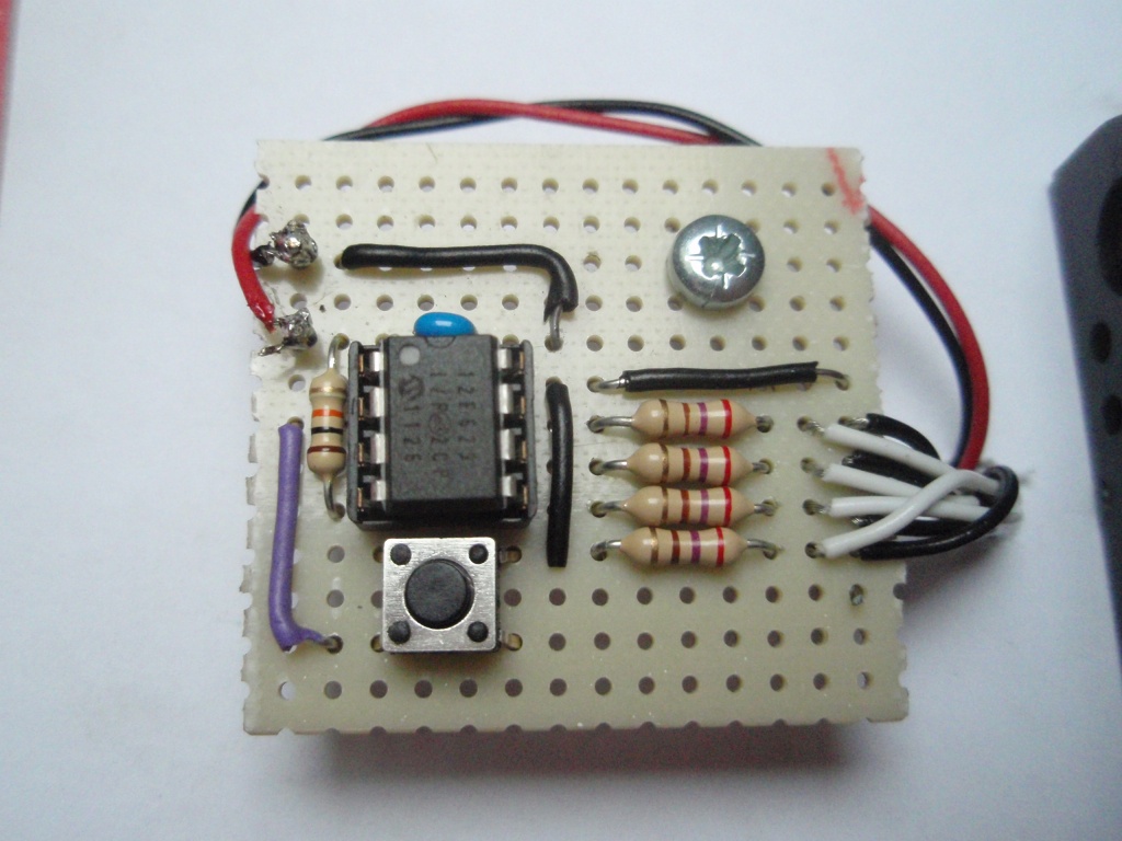
There is no PCB for this
project, with so few components it is simple to construct it on
strip or pad board as shown below.
Notes:
I've not fitted a power on/off
switch. It is shown on the schematic and if required
should be fitted between the lead from the battery pack positive
terminal and the control board.
My demo board is assembled on
an A4 (297mm x 210mm) back board. It was made up to
visualise the application of the project - you'll probably
want to do something a bit more ambitious :-)
You don't have to use all
the outputs if your application doesn't need them. Just
leave them unconnected.
You can attach up to 2
LEDs on each output. You must use a separate current
limit resistor for each LED (see the GPIO2 - pin 5 output
used for the two navigation lights on the schematic diagram)
If you need to drive more
LEDs you will need to add transistors - see
drivingLEDs.pdf
You can use either a PIC12F629 or
PIC12F675 microcontroller with this circuit. The same
firmware code is used with either device. Download
the files required below.
The HEX file is ready to
program straight into the PIC. The ZIP file contains the
source code which you can modify or just view to see how it
works.
Not got a programmer? Buy
a pre-programmed PIC from the On-line store
If you need a PIC Programmer I
strongly recommend the
Microchip PICKit 2,
this is available from suppliers world wide or direct from
Microchip. It's reasonably cheap to buy and reliable.
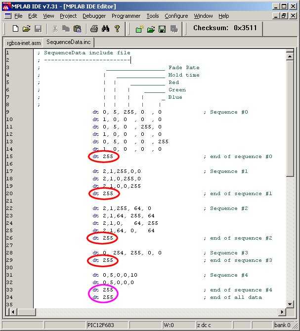
The
data used by the program for the navigation light sequences is
held in the file 'RCnavLightsData.inc' You can edit this
file to add, remove or change the data provided. You must ensure
that it follows the format described. In particular pay
attention to the 'end of sequence' and 'end of all data' markers
and also ensure that each line of sequence data contains five
comma separated entries. (see screen dump below)
A really useful on-line utility for simulating the sequences can
be found here:RGB
LED Simulator (thanks to Marek 'Marki'
Podmaka for creating and sharing this simulator)
This program code used for the Navigation Lights is based on the
RGB Mood Light program code used in projects elsewhere on the
Picprojects website. The format for the sequence data file
is the exactly the same.
In
the screen dump above note the 'end_of_sequence' markers circled
in red and the 'end_of_all_data'
marker circled in purple.
You
must have at least one sequence present up to a maximum of 256
individual sequences, although you're likely to run out of
available memory on the PIC before you reach this limit.
Each line of data starts with
a 'dt' (data table) assembler directive.
All data is specified using
decimal values.
Each data value must be
separated by a comma
The sequence data on each line
has five fields:
Fade Rate: speed the
colours fade from the current values to the new values.
Each step occurs at an interval of 5ms x Fade Rate.
Fade Rate value of 0
indicates the RGB values will be updated immediately
without fading.
Fade Rate value
must not be set to 255 except to indicate end of
sequence. (see e. below)
Hold Time: after fade
completes, delay before moving to next line of data.
Interval is 50mS x Hold Time
Hold Time value of 255
following a Fade Rate of 255 indicates
end_of_all_sequence data.
Red
PWM value. 0 = 0% (LED off) through to 255 = 100%
(LED fully on)
Green PWM value. 0 = 0% (LED off) through to 255
= 100% (LED fully on)
Blue
PWM value. 0 = 0% (LED off) through to 255 = 100%
(LED fully on)
Typically changes in
LED brightness are more noticeable between 0 and 128
than from 128 to 255.
End of the current sequence
data is indicated by the Fade Rate field being set to '255'.
When the application encounters this it restarts the
sequence from the beginning.
At the end of all available
sequence data both the Fade Rate and Hold Time fields must
be set to '255'
After editing RCnavLightsData.inc the file should be
saved and the RCnavlights_main.asm reassembled. The
resulting RCnavlights_main.HEX file can them be
programmed into the PIC.
For
additional information on editing and reassembling code use
MPLAB see my
MPLAB How-to page