Do a search on YouTube and
you'll turn up literally dozens of video clips of LED cubes,
small 3x3x3 cubes, bi-colour, RGB and mono cubes, amazing
16 x 16 x 16 RGB cubes. However, very few show you how to
make one and provide the firmware.
The cube described on this
page uses a 5 x 5 x 5 matrix of single colour LEDs. This is
a good size to experiment with as the number of LEDs
required at 125 keeps the cost down, doesn't take too long
to assemble and just fits onto a eurocard sized PCB. The
power requirement is under 1 amp and the use of just one
colour keeps both the hardware construction and control
software fairly simple.
The project includes a
ready to program HEX file with some demo cube animations and
also the source code. The firmware implements a simple
macro
drawing processor command set so if you've got some
programming skills you can create your own animations for
the cube.
Although the project on
this page uses a PCB, the original prototype (see below) was
constructed on a prototype pad board so if you're not able
to make your own PCB it's still possible to make this
project yourself.
Bigger cubes:
The 5x5x5 LED cube project
shown here is a great size if you want to have ago at
building a LED cube.
Why? because it gives a good balance between the number of
LEDs and therefore cost and time needed to assemble it and
the overall 3-D effect. 8x8x8 or even 10x10x10 cubes
look good and it doesn't sound much more work than a 5x5x5
cube but you're going from 125 LEDs to 512 or 1,000 LEDs in
a 10x10x10 cube - that's a lot of work.
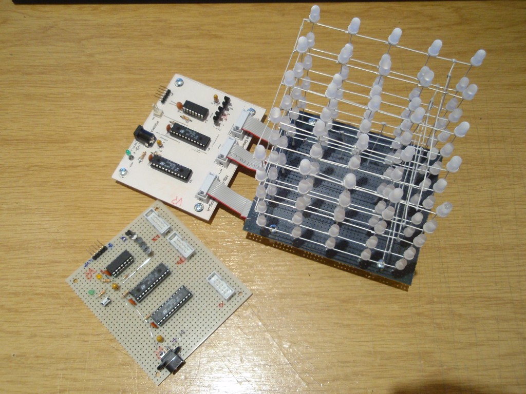
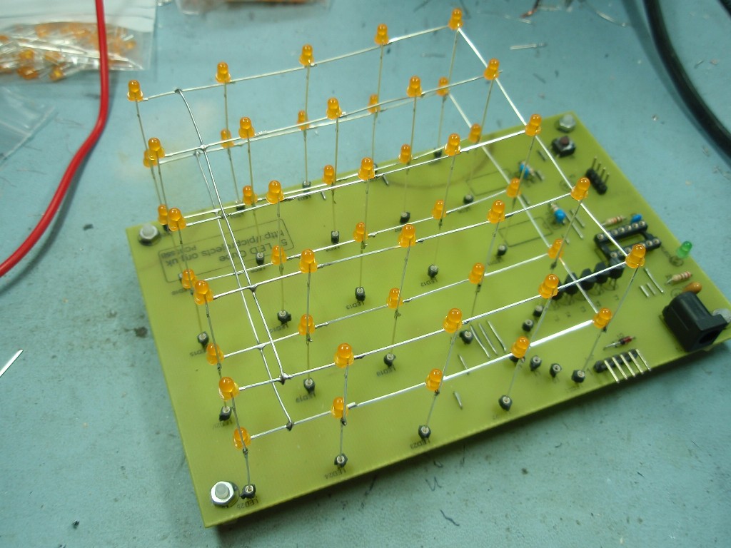
prototype controller
prototype controllers and
LED cube
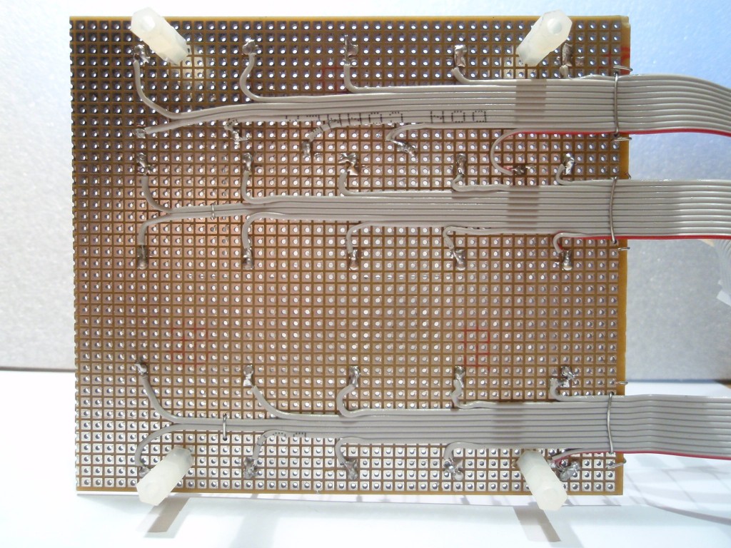
Underside of prototype LED cube
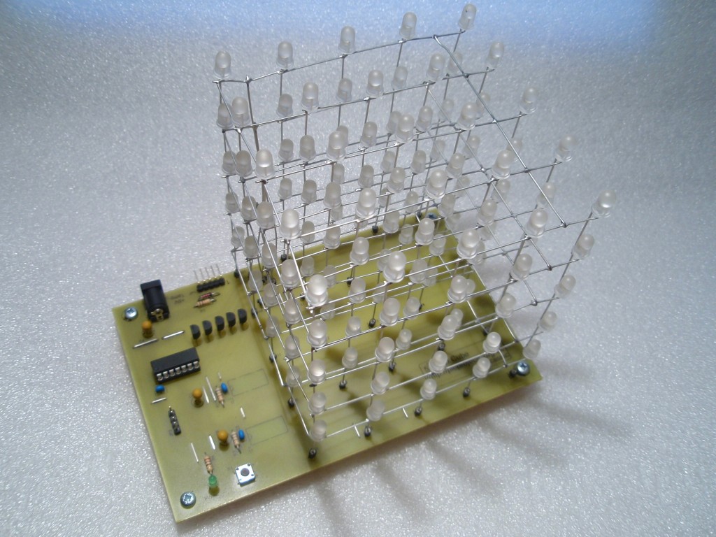
All lit up; orange 3mm LEDs
LED Cube running
latest ledcubeC3.hex firmware showing all 28 animations
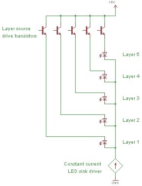
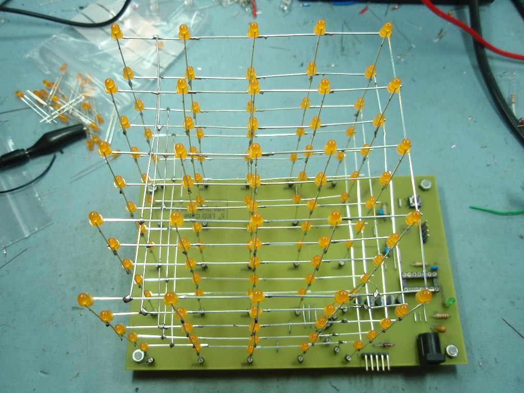
The LED cube is made up
from 125 LEDs arranged into 5 layers of 25 LEDs each. The
display itself is multiplexed so instead of requiring 125
connections it requires one to each of the five layers and
25 to each LED in a layer making a total of 30. The cube is
refreshed by a software interrupt routine with each layer
active for 2ms, so the entire cube is refreshed every 10mS
(100Hz). This results in a display with no visible flicker.
Only 8 I/O lines are
needed to control the LED drivers for the cube which allows
a tiny 14 pin PIC
16F688 microcontroller to control the whole cube. This
micro has an internal 8Mhz clock and 4Kwords of program
memory.
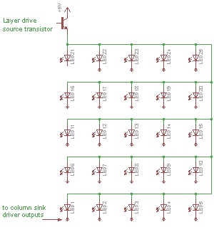
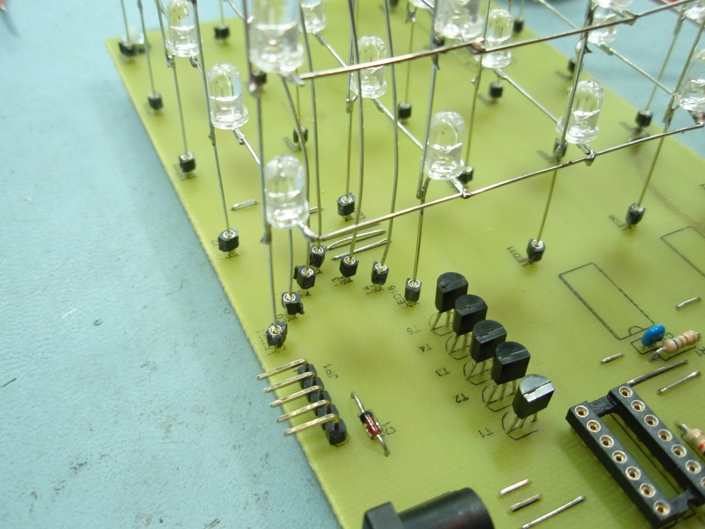
Each of the LED layers is
arranged in a 5 x 5 matrix and controlled by a transistor in
an emitter follower configuration connected to the LED
anodes. When the respective layer control output from the
PIC goes high the base of the transistor is held at +5V and
the emitter sits approximately 0.7 volts below this. The
transistors used are BC637 NPN transistors, if an
alternative is used it should be of similar specification,
have an Ic rating of at least 1 amp and check the pin out.
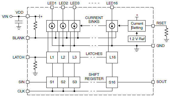
The cathodes of the LEDs
are connected to IC2 & IC3. These are CAT4016 low voltage
16-bit constant current sink drivers. The LED current is
set by a single resistor connected to the RSET input
of the IC (pin 23). The 1K8 resistor (R1 & R2) set the LED current
to ~33mA; this resistor can be altered to vary the current
supplied to the LEDs.
(consult the
datasheet
CAT4016 before altering the value of this resistor).
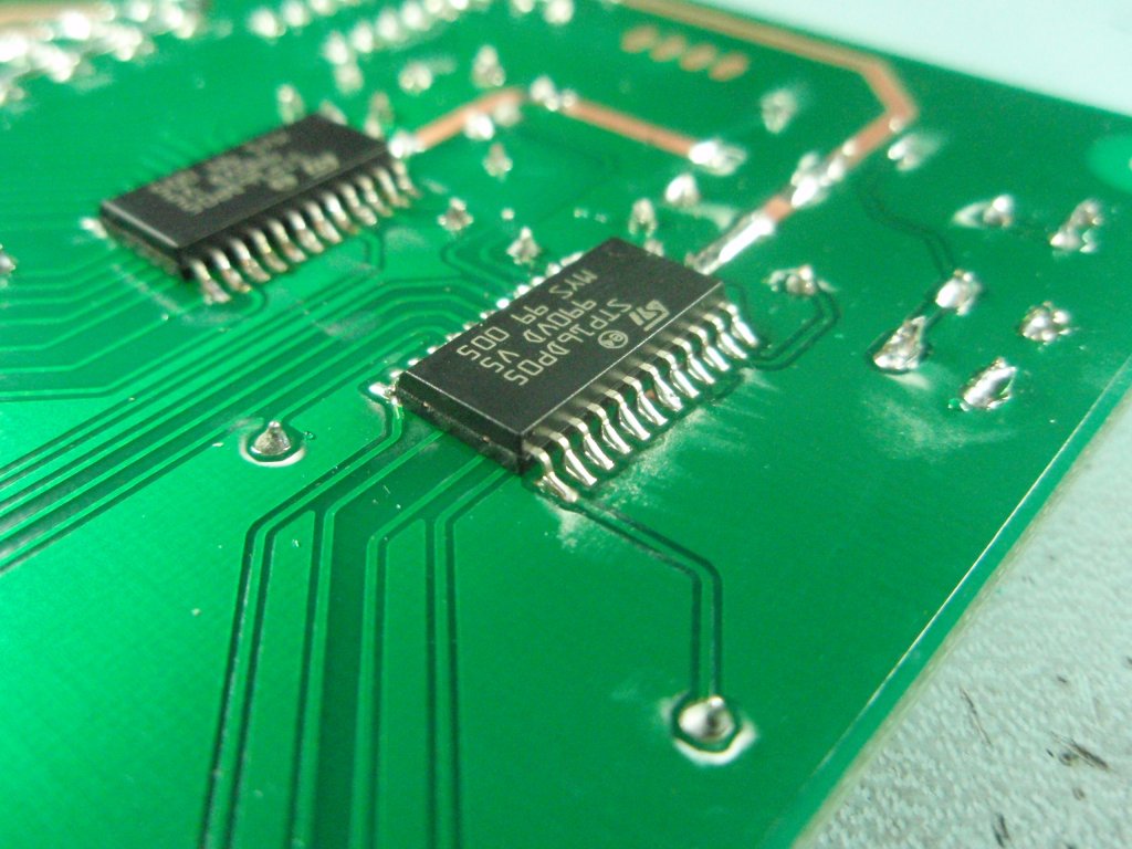
LED Cube kits after
10-March-2012 ship with the STP16DP05 driver IC. This
is functionally equivalent to the CAT4016 but requires 620R
resistors for the current setting since it uses a different
ratio in the current mirror circuit. (Datasheet for
STP16DP05)
Only change the resistor to reduce LED current, the circuit
design shown may not work at higher LED currents and
components may be damaged.
One layer of the cube
One column of the LED cube
The advantage of using a
constant current sink driver IC's is that almost any LED can
be used and the supply current remains constant regardless
of the LED forward voltage. If the output current does need
to be altered, it only requires the two current setting resistor
to be changed.
The outputs of the current
sink drivers (IC2/IC3) are controlled by the LED data loaded into
by the PIC microcontroller.
The driver ICs each contain 16 shift registers and an output
latch. The PIC presents 1-bit of LED data to the serial
input of IC2 (SIN). The PIC then generates a pulse on the
CLOCK input of both driver ICs to shift the data into them. The two driver ICs are cascaded
(SOUT of IC2 feeds SIN of IC3) so
the PIC simply clocks in 25 bits of data. Once all 25
data bits have been sent to the driver ICs the LATCH signal
is pulsed to place the data on the current sink outputs.
The PIC then sets the respective layer drive transistor output
high which turns on the required LEDs in one layer.
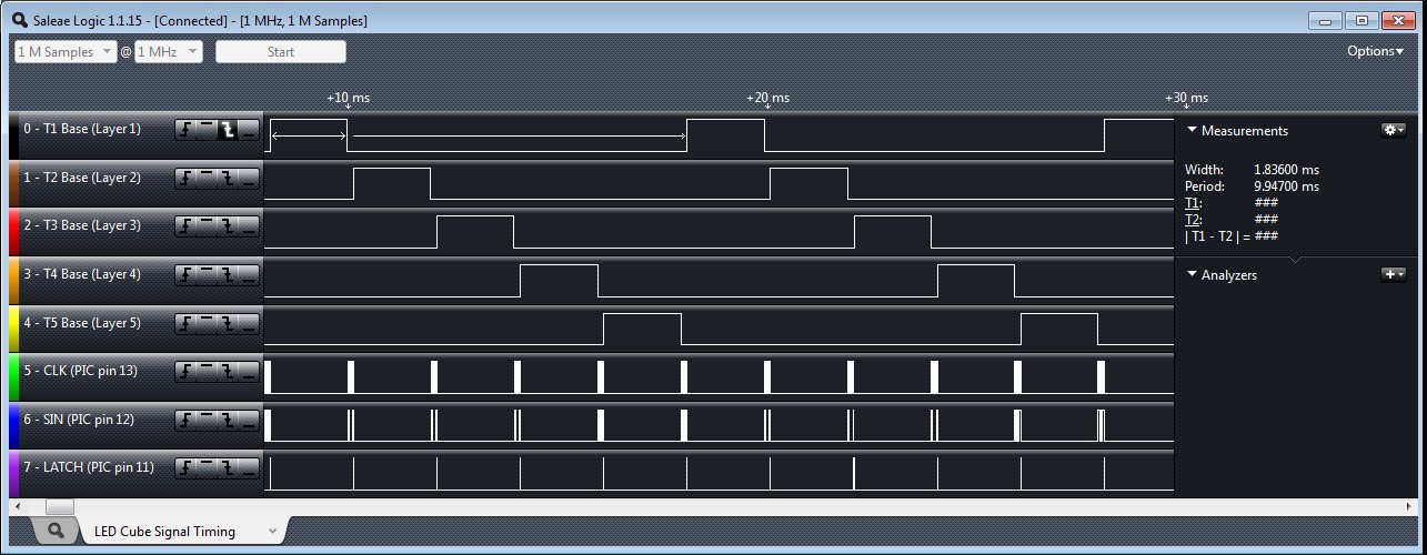
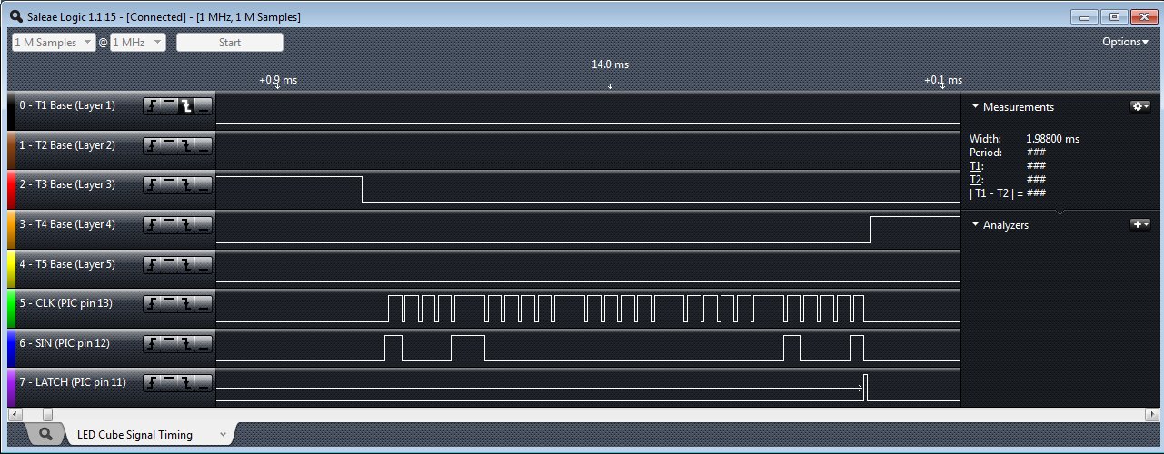
The three
timing diagrams below are taken from an operating LED Cube
using an 8-channel logic capture tool. This
information is provided to show the actual signals generated
by the PIC microcontroller that control the LED cube.
Hopefully this clears up any ambiguity about how the
hardware works.
(You don't need to know about this to construct a working
cube, it's just for the techy ones out there)
Transistor base terminal layer drive signal timing.
You can see the firmware takes about 10mS to scan all 5
layers.
You can also see that a layer is turned off before the
new layer is turned on.
This prevents ghosting between the layers (the diagram below
shows it better)
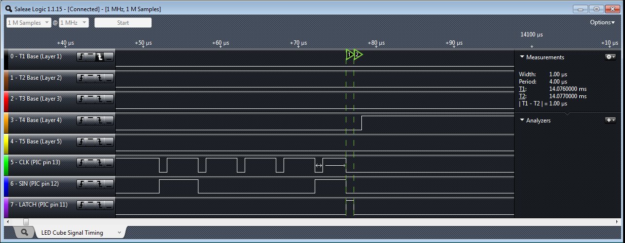
Serial data
load signal timing from PIC (IC1) to CAT4016 (IC2) for one
layer.
In this timing diagram you can see the CLK signal appears in
5 groups as the
software clocks in five groups of five bits making up the 25 LEDs of one
layer.
The SIN data is shifted into the IC2/IC3 on the rising edge
of the CLK signal.
Serial
data latch timing (expanded view of previous diagram)
When all 25 bits have been clocked into IC2/IC3, the latch
signal transfers the data to the driver outputs
Capacitors C1-C6
The six capacitors C1 - C6 (3 x
100nF & 3 x 3.3uF)) provide
power supply decoupling. C4 and C5 in particular are
important and should be tantalum bead (or low ESR
electrolytic) types located close to
the Vdd power pin of the two driver ICs.
Original design used 10uF
capacitors for C4/C5/C6. The value of these capacitors has
now be changed to 3.3uF
If you are building the LED Cube from the schematic place a
3.3uF and 100nF capacitor close to the Vdd power pin of each
of the three IC's in the circuit. You have then used all six
capacitors shown on the schematic and placed them where they
are needed.
JP1 & D1
The JP1 (ICSP header) allows
in-circuit programming of the PIC microcontroller. It will
work with the genuine Microchip PICKit2 programmer and I've
also tested with several clone versions of the PICkit2. I
don't test with any other types of programmer.
Diode D1 allows the PIC
programmer when attached to J1 (ICSP header) to detect power
on the target board while preventing it from actually
powering the target. Depending on your particular
programmer this diode may be omitted altogether, but if in
doubt fit it. If you don't intend to program the PIC
in-circuit you don't need the diode. This diode is not
needed when using the Microchip PICkit2 programmer
JP2 Pin header JP2 provide
+5volt and Gnd connections and also brings out the PIC I/O
port pins RA4 and RA5. RA4 is also connected to the switch
S1 on the PCB. These are made available for those of you
who want to add additional features to the software.
Power LED The power LED is not critical, you can use
almost any 3mm LED for this, or omit it altogether if you
don't want a power indicator.
DC Power Jack J1
Power to the circuit is provided through the DC input jack
J1. This should be connected to a 5 volt regulated
power supply capable of supplying at least 1 amp. The power supply should also be
able to maintain regulation while the load switches between
15mA to around 800ma every 2mS, all the plug-top style ones
in my workshop work fine but if you have problems this is
something to check.
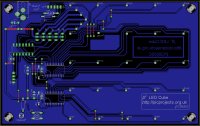
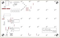
The circuit has been
designed to fit onto a single sided 160mm x 100mm eurocard
size PCB. The single sided design makes home production of
the PCB straightforward.
You can buy all parts
needed to build this project from most component suppliers
world wide. In the UK you can get everything except the
STP16DP05 from Rapid Online and I've included a parts list with
their part numbers below.
What LEDs to use
The
overall effect of the LED cube can vary enormously, so
choosing and using the right type of LEDs is important.
This section gives some tips and suggestions on the type of
LEDs to use.
For the main cube LEDs you
can use virtually any 5mm or 3mm LEDs you want. Some LEDs
are better suited for use in a cube than others so here are
some tips.
The longer lead on the LED
needs to be at least 25mm in length in order to form the
cube. Until recently I had not come across LEDs with
leads shorter than this but as of 2014 it would appear that
there are LEDs out there with short leads. Since the
PCB is laid out with the columns spaced at 23mm, LEDs with
shorter lead lengths won't reach the next LED to solder them
together.
In my opinion the cubes
made with 3mm LEDs in diffused packages work best, there is more space within
the cube body which makes it visually more effective and the
diffused body distributes the light better.
Water clear packaged LEDs
are not very effective since the LED illuminates the one
directly above it. High brightness LEDs are even worse in
this respect and LEDs with 15o viewing angle are
hopeless in my experience. LEDs with outputs around
50-150mcd seem to work quite well.
If you can get LEDs in a
milky white diffused package these are ideal, however they
are generally not that easy to find.
If you have LEDs in a clear
package you can diffuse them using
Plasti-Kote Glass Frosting spray. This works quite well but
don't spray the LEDs until they've been assembled in the jig
otherwise the jig rubs the coating off the side of the LEDs.
One difficulty I've found
is that you can find two different LEDs that on spec' appear
to have similar light output, but when you compare them in
use one is much brighter.
Therefore if you can it's worth experimenting
with different LEDs before assembling an entire cube. You
can put together eight LEDs in to a 2 x 2 x 2 cube; connect it
into one corner of the driver PCB to get an idea of whether
a particular LED is going to work effectively.
Finally, the cube needs 125
LEDs, buy a couple of extra ones so you have spares in case you get a
faulty one, lose one etc.
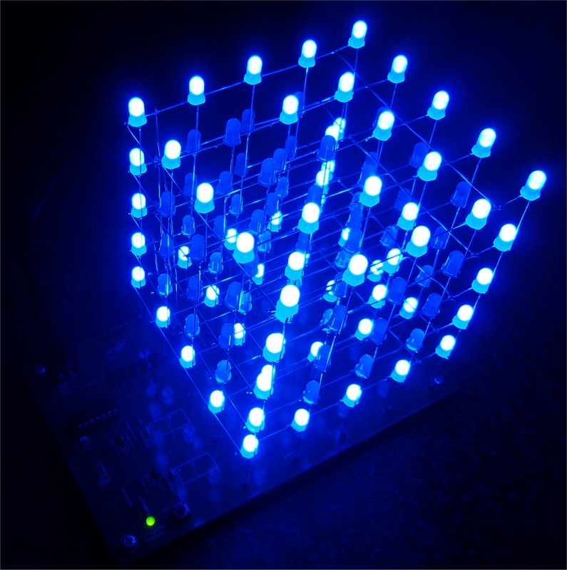
If you are in the United
Kingdom, check out the 5mm Colour Diffused LEDs from
www.goodwillsales.com. The cube shown in the photo
(right) was constructed using their blue 5mm diffused LED
and is very effective.
All Rapid
parts/descriptions correct at 13-December 2012. You should
check part# and descriptions are correct when ordering in
case I've made a mistake transferring them onto this page.
Component
Description
Part #
R1,2
(order 1 pack)
620r
0.25w Metal Film Resistor Pack of 100
62-0807
R3 (order 1
pack)
PACK 100 10K 0.25W
CF RESISTOR (RC)
62-0394
R4 (order 1
pack)
PK 100 270R 0.25W
CF RESISTOR (RC)
62-0356
C1,2,3
100N 2.5MM X7R DIELEC.CERAMIC (RC)
08-1015
C4,5,6
3.3uF 16V TANTALUM
BEAD 5MM (RC)
11-0636
Cube LEDs
(order 125+)
see text above
-
D1 (see note 1)
BAT85 SCHOTTKY
DIODE 30V DO-34 (RC)
47-3108
Q1,2,3,4,5
*
BC635 TRAN NPN 45V
1A TO92 TRUSEMI RC
81-0075
IC1
PIC16F688-I/P
MICROCONTROLLER 8-bit DIP14 (RC) Requires programming. You can buy the
pre-programmed PIC16F688 from Picprojects online shop.
73-3698
IC2,3
(see note 2)
STP16DP05MTR SO24 16
BIT LED DRIVER (RC) See below for alternative parts
n/a
LED1
L-7104GD MINIATURE
3MM GREEN LED (RC)
55-0105
socket for IC1
14 PIN 0.3IN DIL
SKT (RC) (Tube of 34)
22-0108
J1
2.1
PCB DC POWER SOCKET (RC)
20-0970
JP1
(see note 1)
5 WAY
R/A SINGLE ROW PLUG (RC)
22-0710
JP2
(see note 1)
4 W
SINGLE ROW PCB HEADER PLUG RC
22-0505
S1
TACTILE SWITCH 6X6MM HEIGHT 5MM (RC)
78-0621
LED
matrix sockets
32 WAY
TURNED PIN SIL SOCKET(RC)
22-1751
Power
supply
5V
1.5A MINI PLUGTOP SW MODE PSU RC
or
15W Mini Plugtop PSU 5V DC 2.5amp
85-2955
85-2900
*
You can use BC635, BC637 or BC639 interchangeably for the
transistors Q1-Q5. Whichever is cheapest / easiest to
source.
note 1:
JP1, JP2 and D1 are not required to build a working LED
cube. These parts are not supplied with the either the 555FSK
or 555LED kits.
note 2:
Alternative LED Driver parts for IC2 & 3
The STP16DP05MTR driver is
available from RS
Components.
You can also use alternative parts listed below. You
will need to use the correct LED current limit resistor
shown in the table if you use an alternative part.
Those listed as tested have been used to build working LED
Cubes. The other parts are equivalents that should work okay
but I've not actually built a cube using them.
All these parts are
functionally the same; they are just made by different
manufacturers. Any one will work equally well in the
LED cube circuit. No one is better than another,
so use whatever you can get hold of at the lowest price.
The PCB for the LED Cube
project is designed for a SO24 (SOIC-24) package. All
the parts above come in different package types so you
should check the suppliers description before ordering to
ensure you are buying the correct package type.
Power Supply Mishaps
We've sold lots of kits for
the LED cube and on the whole there have been no problems
getting the kit to work.
However, a number of times
now people have connected the wrong power supply to the
board, in several cases they had it working with the correct
5 volt power supply but they have just picked up the wrong
PSU by mistake and damaged a working board. I've done
it myself so I speak from experience.
Tip. Put some tape or other marking
on the end of the power jack lead to make it stand out from
all the other DC power jacks you may have around. This
will help avoid picking the wrong one by mistake.
The original board design
does not have protection for over-voltage or reverse supply
connection. Any voltage above 5 volts, or a reversed power
connection will destroy components on the board.
The driver
chips IC2/3 are the most likely to fail.
If the voltage applied
is >10 volts it will damage or destroy the tantalum
capacitors C4/5/6
If one shows visible signs of damage, replace all of
them.
Note: From February 2013 kits have been supplied with
3.3µF
/ 16 volt tantalum
capacitors. These capacitors will not be
damaged by voltages below 16 volts.
The PIC
microcontroller is a little more robust and may well
survive a few seconds, but given a
high enough voltage or long enough and it too will fail.
Because the PIC
microcontroller has input protection diodes connected to the
power rails, the board may actually survive a reversed power
connection. This does however depend on the power
supply and the length of time it's connected so expect the
worst.
Finally, if you do have a
power supply accident, contact us and we can sort out
replacement components for you at a very reasonable cost.
Soldering the surface mount
parts and assembling the LEDs into a cube are not jobs for a
novice electronic kit builder, don't attempt this project
unless you are confident of your ability and have the
necessary skills and equipment.
Whatever your ability
level please take time to read through this section once
before starting construction and refer to it again during
construction. You are also advised to refer to the
schematic diagram.
Assembly is in two stages;
control PCB and LED cube. It's easiest to assemble the LEDs
into a cube using the PCB to hold it in place so I suggest
the PCB is assembled first.
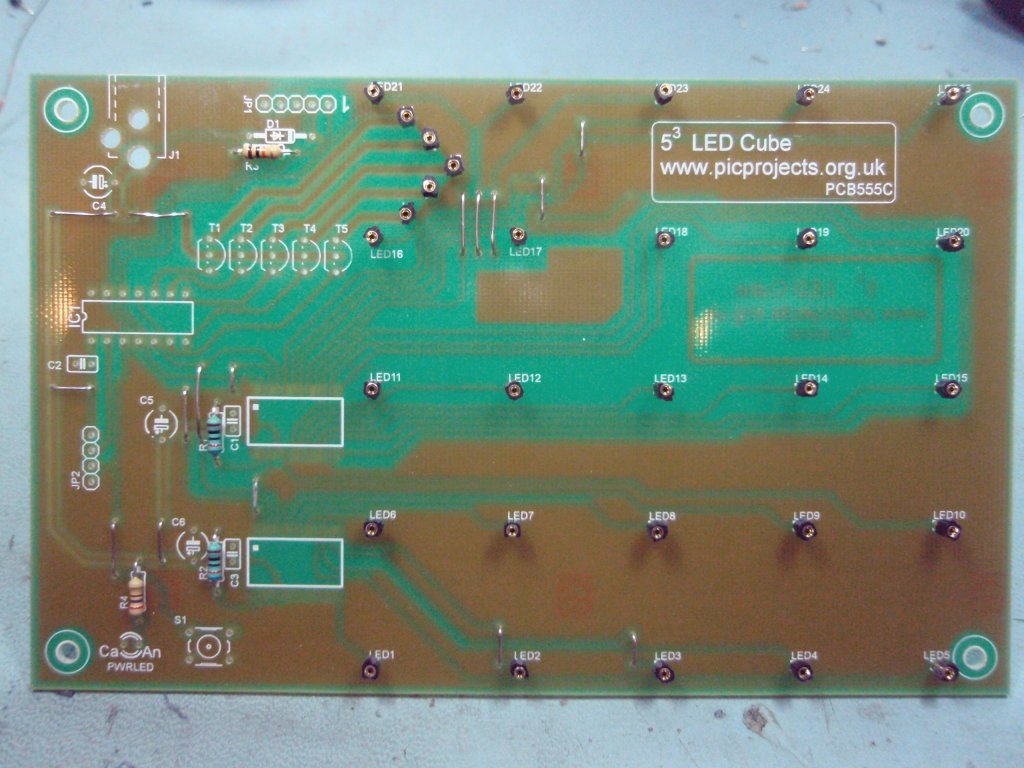
Fig. 1 Check the PCB
to make sure all the holes have been drilled, and look for
any etching faults, bridges, breaks etc. before commencing
with the assembly.
When you're
trimming the excess leads from components and link
wires DO NOT lift or twist the side cutters
as you make the cut. If you do there is
a risk the copper PCB track will break at the edge
of the solder joint. It's very difficult to
see at the joint but it's a common cause of faults.
If it does happen it's easy to repair, just scrape
off 3mm of the solder resist from the track as it
meets the joint and bridge with solder.
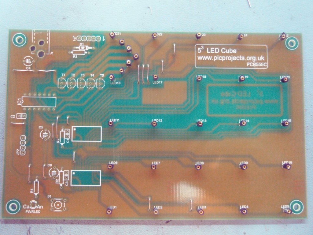
Fig. 2 The design
has deliberately been kept to a single sided PCB, however
this has meant 16 wire links are needed to interconnect
tracks on the copper side. You should start by installing
these wires.
Fig. 3 The
PCB supplied in the kit is a professionally
manufactured board with screen print and solder
resist mask.The
silk screen overlay for the PCB doesn't show the
location of the 16 link wires. The location of the links
is indicated by the yellow lines overlaid on the
photo.
(download PDF version of
this image
)
Fig.4
Fig .5
Fig. 6
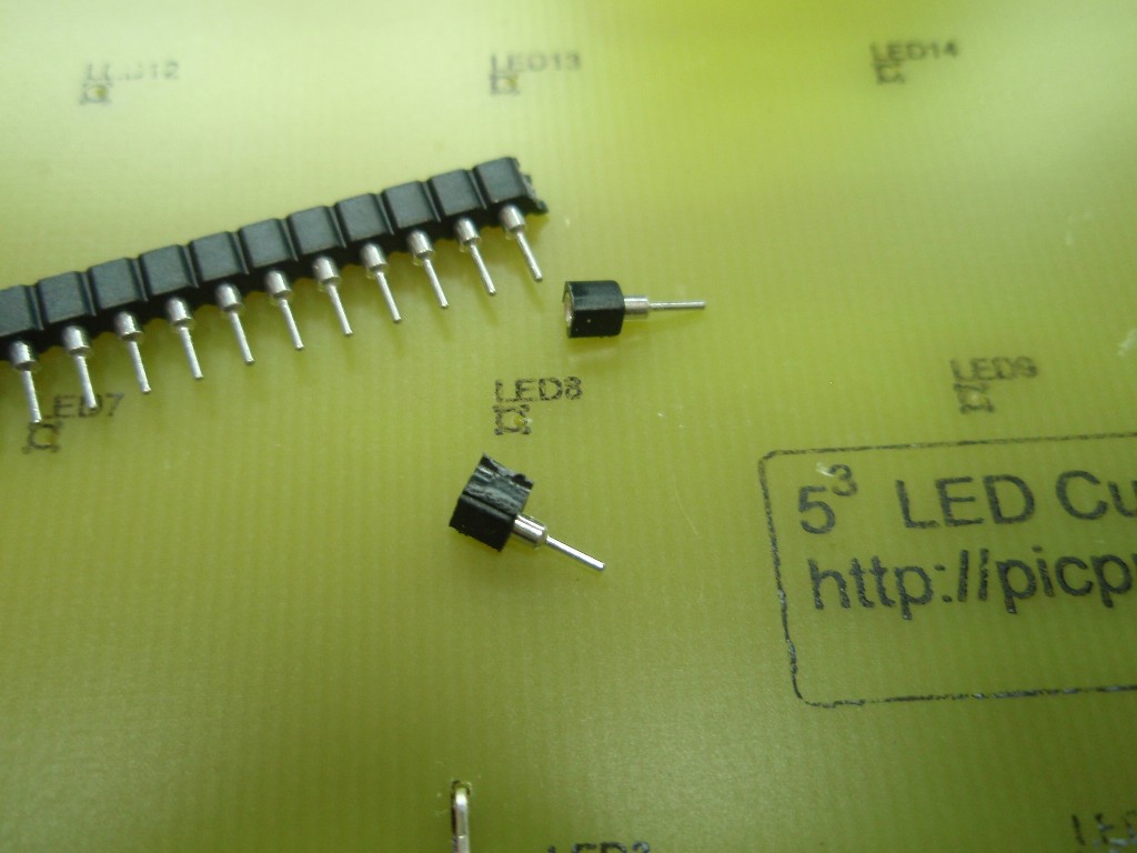
Fig. 4/5 Snap the SIL socket in to individual pins
(use a knife) and then solder one in to
each of the 25 LED holes and 5 layer drive connections.
(you can of course solder the LEDs of the cube directly to
the PCB, however it makes repair and removal of the cube
difficult should you have a fault or wish to swap cubes) (The kit includes a 32 way SIL socket strip, you only
need 30 so you have two spare)
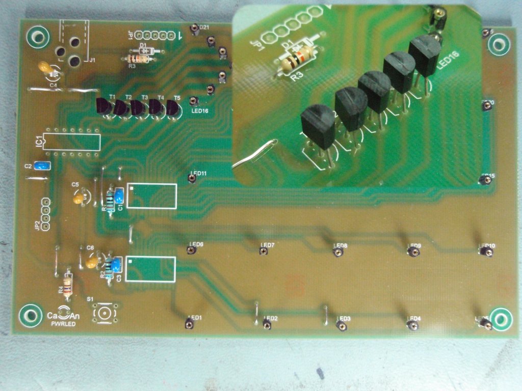
Fig. 6 Install the
resistors.
Colour value bands on the
resistor body are:
Depending on the driver ICs used for IC2/3 you will need to
fit different value resistors for R1/R2.
If you are using the
CAT4016 driver for IC2/3 resistors R1 and R2 should be
1K8
1K8 (brown-grey-black-brown-brown)
If you are using the
STP16DP05 driver for IC2/3 resistors R1 and R2 should be
620R
620R
(blue-red-black-black-brown)
If you have bought
the LED Cube kit #555FSK from the Picprojects eShop, it
will include the correct value resistors for use with
the driver IC's supplied in the kit.
R3 is 10K (brown-black-orange-gold)
R4 is 270R (red-violet-brown-gold)
D1, JP1 and JP2 are not included with the 555FSK kit and are not required
to build the working cube.
Fig.7
Fig .8
Fig. 9
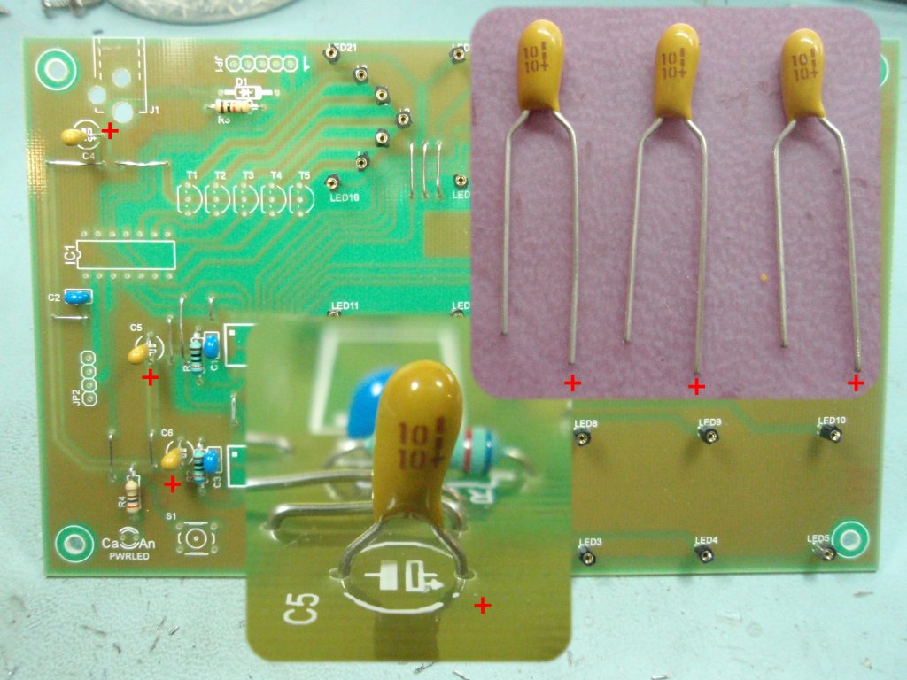
Fig. 7 Install the
capacitors. There are six in total. C1/2/3 are 100nF
and are not polarised so it doesn't matter which way round
they go.
C4/5/6 are either 10uF or
3.3uF Tantalum
capacitors. These must
be fitted the correct way round. There will normally be a
vertical line and/or '+' symbol on body of the capacitor above the
positive lead and one lead is normally
longer than the other; the long lead is the '+' positive lead
(see photo).
Fig. 8 Install the 5
transistors, again ensuring they are positioned as shown on
the overlay.
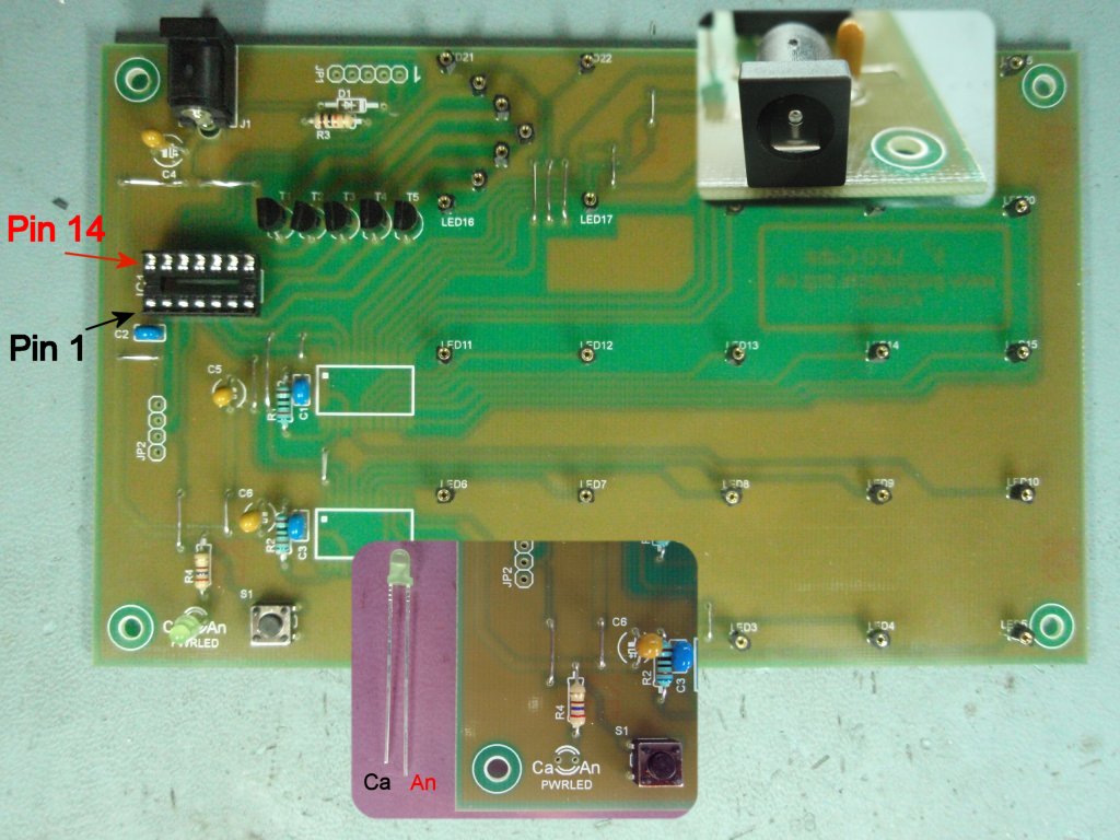
Fig.
9 Finish the upper side of the PCB by installing
the LED, switch, pin headers and sockets. When
installing the LED fit the cathode lead into the hole marked
'Ca' on the PCB. The LED cathode lead is the shorter
of the two leads.
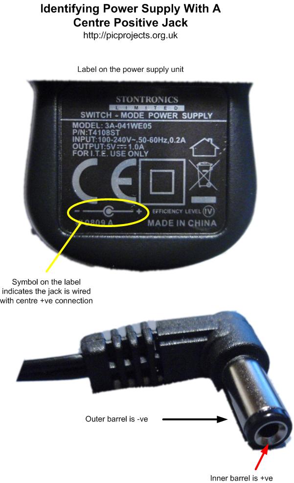
At this point, apply 5
volts to the DC input jack and take note of the following:
The DC jack requires a
centre +ve input connection. As there is no
reverse polarity protection on the board you must ensure
the power supply connector is correctly wired or you
will destroy components on the board.
You must use a 5 volt
regulated DC power supply.
Use a multimeter to ensure
there is nominal 5 volts (4.8 volts to 5.25 volts) present between pins 1 and 14 of the IC1
socket. If not find the fault and correct it before
proceeding.
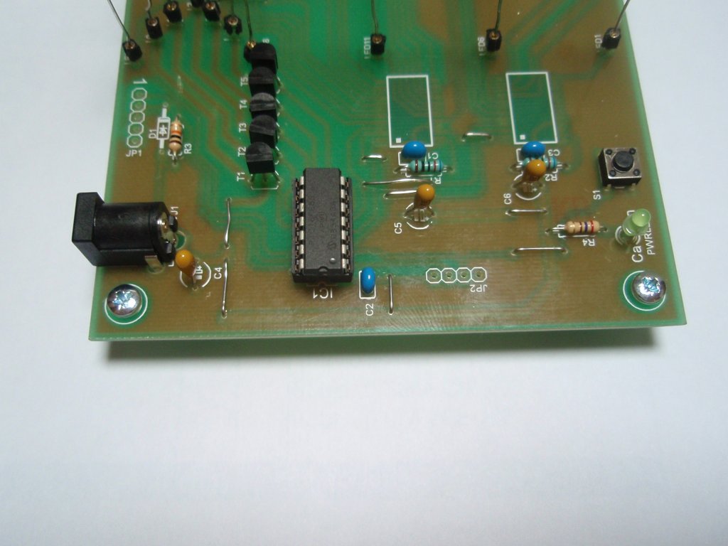
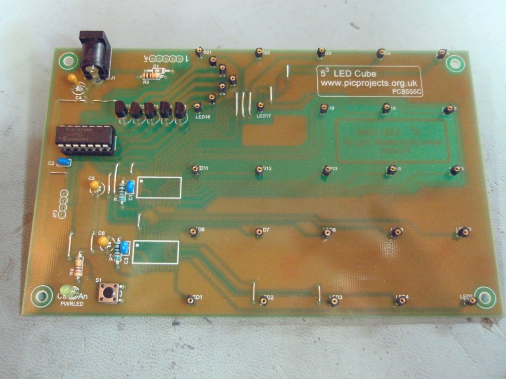
Fig.10
Fig .11
Fig. 12
Fig.
10/11 Views of the assembled PCB from different
angles.
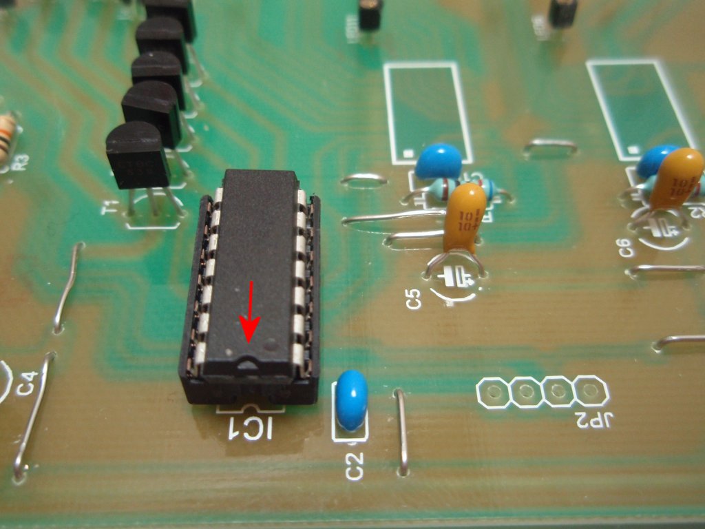
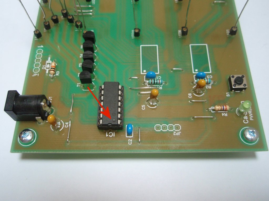
Fig. 12
Note the polarity marking on the Tantalum
capacitor C5. Install the PIC16F688. Into the socket so the
indent is towards the edge of the PCB (arrowed in
photo)
In this section we
look at fitting the two surface mount driver IC's.
These two ICs
have 0.5mm wide pins with 0.5mm space between each
pin. They are not easy to solder so you will
need the following:
Good lighting
in the work area.
It's
difficult to solder these two parts with the naked
eye so I strongly advise the use of a bench
magnifier.
A suitable
soldering iron:
I generally like to solder SMD parts with a 0.8mm chisel bit.
Solder: Use
thin solder 24swg (0.6mm) or even 26swg
(0.46mm). Also lead free solder is much
harder to work with. For hobby use you
might want to get hold of some 60/40 tin-lead
electrical solder.
Lead free
solder, thicker solder (22-18swg) and/or a
larger solder iron bit are much more likely to lead to
bridges and shorts and generally messing up the
assembly.
With care you can easily solder each pin
individually and make a neat, clean job of it. The PCB you can buy from the
online store has a solder
resist mask which reduces the chances of bridging,
though you still need to take care.
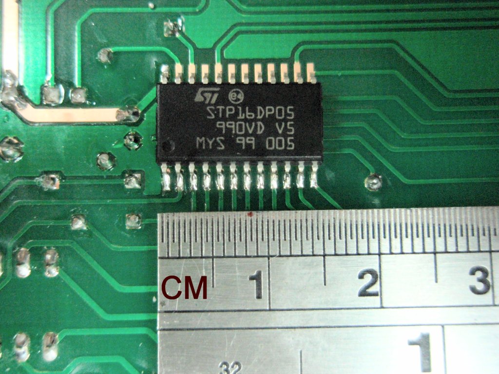
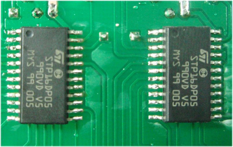
#555FSK kits sold from the
Picprojects eShop will contain a pair of
STP16DP05 driver IC's
STP16DP05
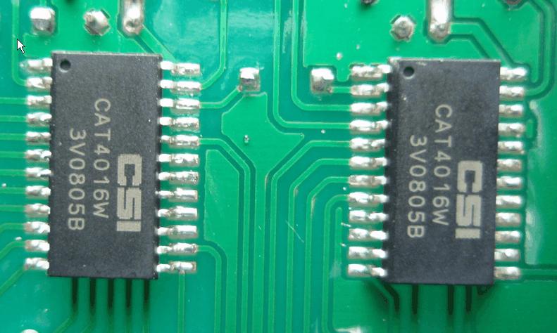
CAT4016
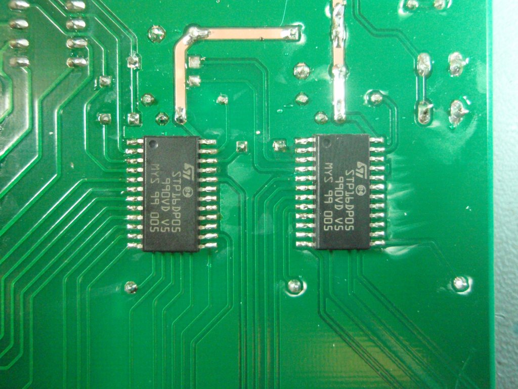
Fig.13
Fig.14
Fig.15
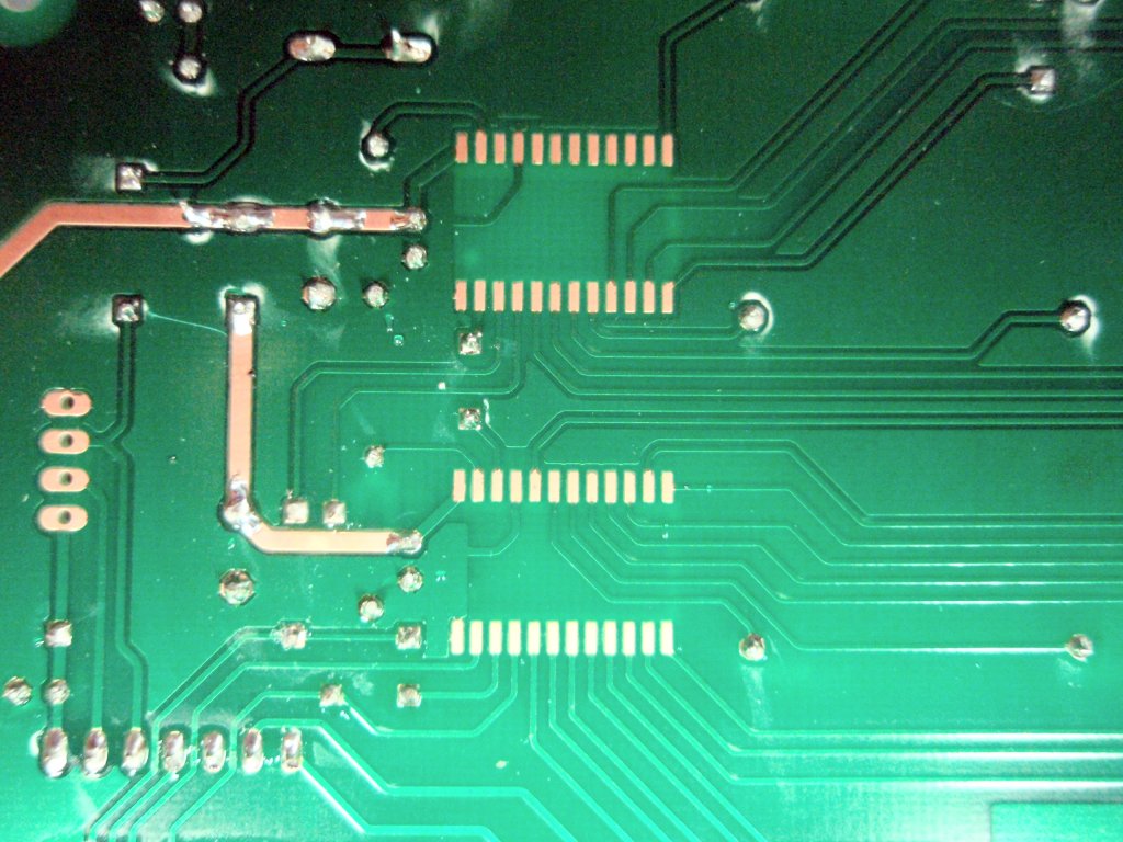
Fig.13
This is the underside of the PCB showing the
location of IC2/3. The IC's are identical so it
doesn't matter which one goes on which pads.
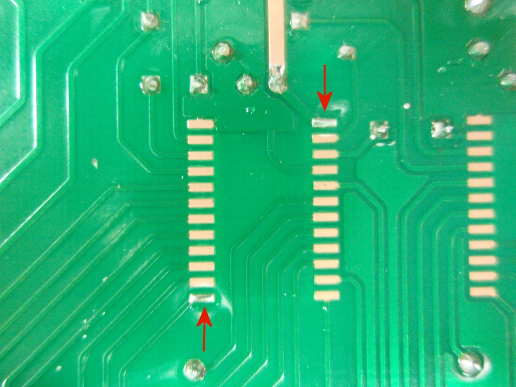
Fig. 14
Use solder to tin the pads with a thin layer of
solder at the two
opposite corners. This will make the next step
easier.
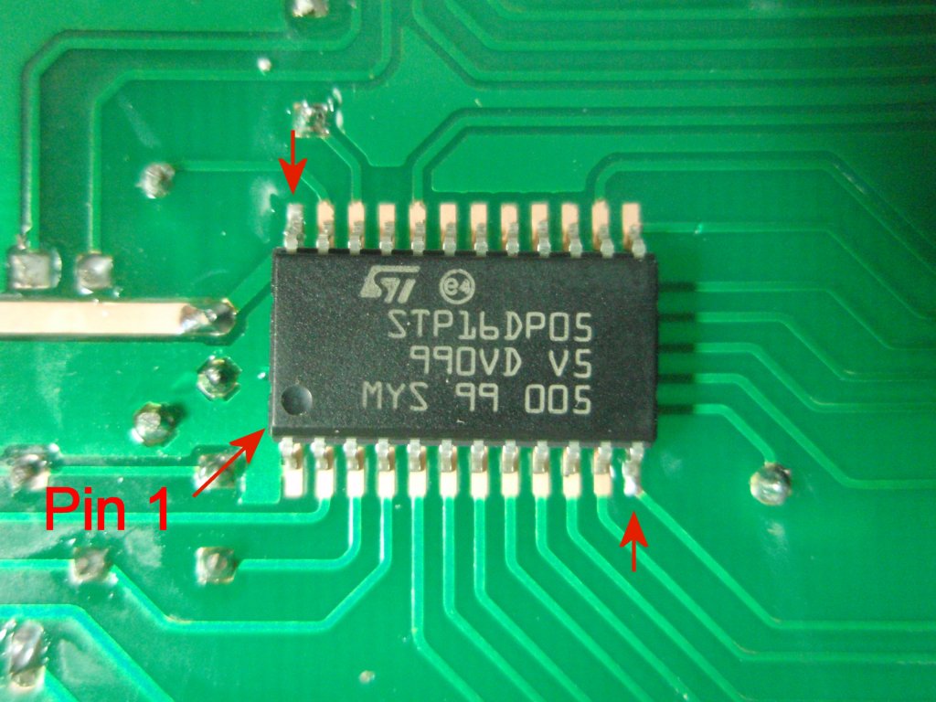
Fig. 15
Locate the IC on top of the pads. You must ensure the IC
is fitted the correct way round. The photo shows a small
dimple on the top of the IC package (bottom left). This
denotes pin 1.
Carefully align and centre
the package over the solder pads, then solder the corner
lead on one side.
Check the package is still aligned and
then solder the opposite corner on the other side of the
package.
With only the
two corner leads soldered it is easy to re-melt
the joints and reposition it if necessary.
Once you are
happy it is aligned correctly over the solder
pads proceed to solder the
remaining leads.
Check
to make sure there are no solder bridges between any of the leads. If you
do get a bridge use some solder wick (copper braid) to
remove it.
Once all the pins are soldered to the PCB you will
need a heat gun to remove it so you need to get it
right first time.
You may have read elsewhere a technique for soldering the
surface mount parts where a large soldering iron bit is used
to cover all the pins in lots of solder then the excess is
removed using solder wick or some other method.
DON'T DO THIS.
Fig.16
Fig.17
Fig.18
Fig. 16
/17 Once you have aligned the IC you can solder
the remaining pins to the solder pads.
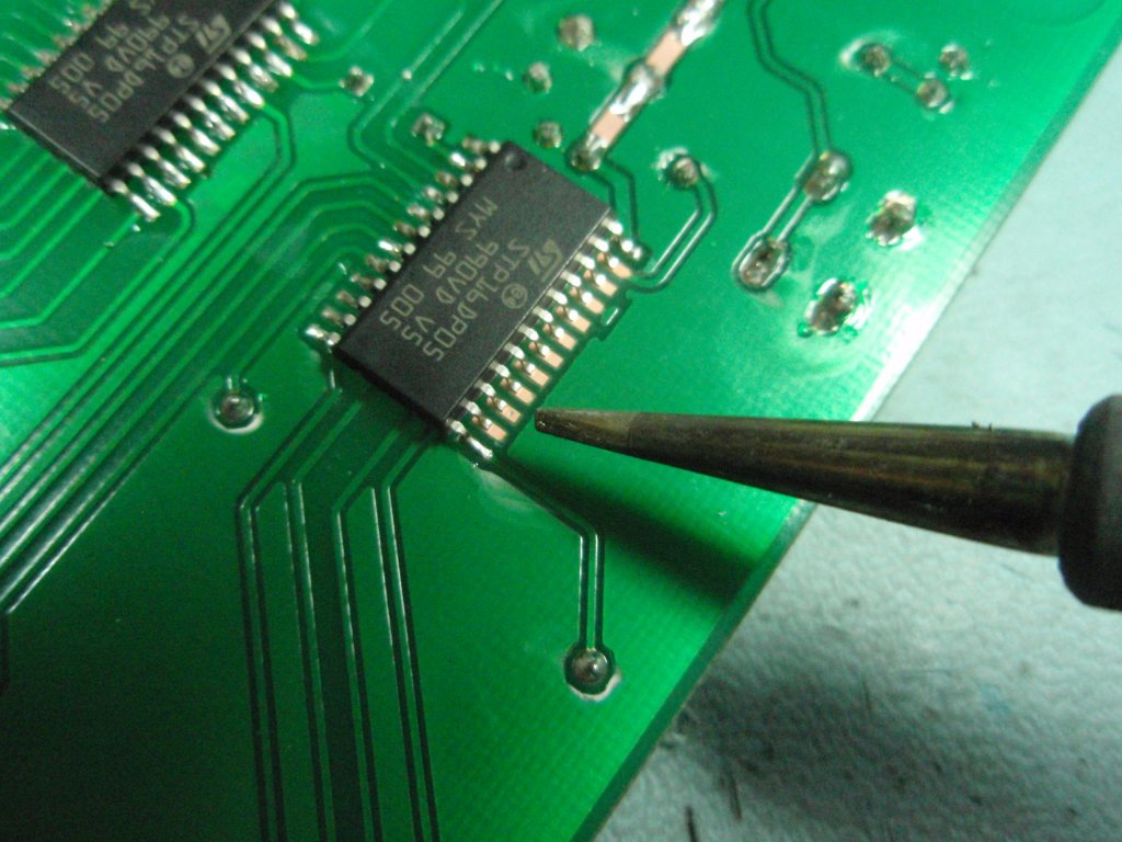
Fig. 18
Once the first IC is solder in place, follow the
same procedure with the second IC
Fig.19
Fig.20
Fig.21
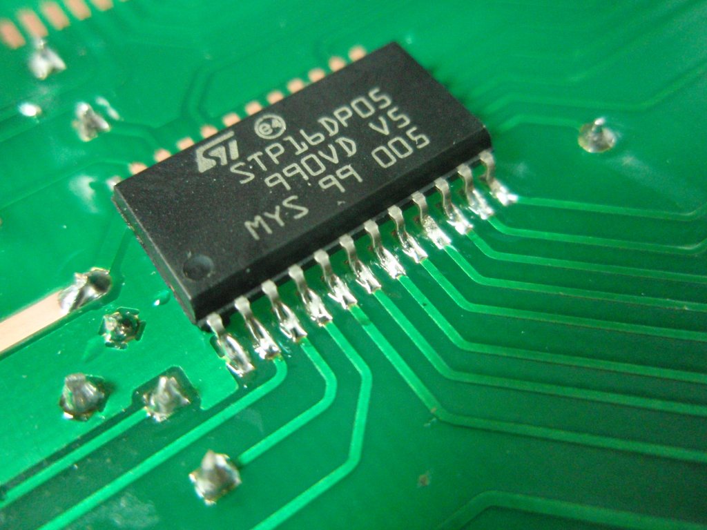
Fig.19
I soldered this board with a 1.2mm chisel tip, I'd recommend
a 0.8mm bit but as you can see it is possible to make a
neat, clean job of soldering these parts by hand.
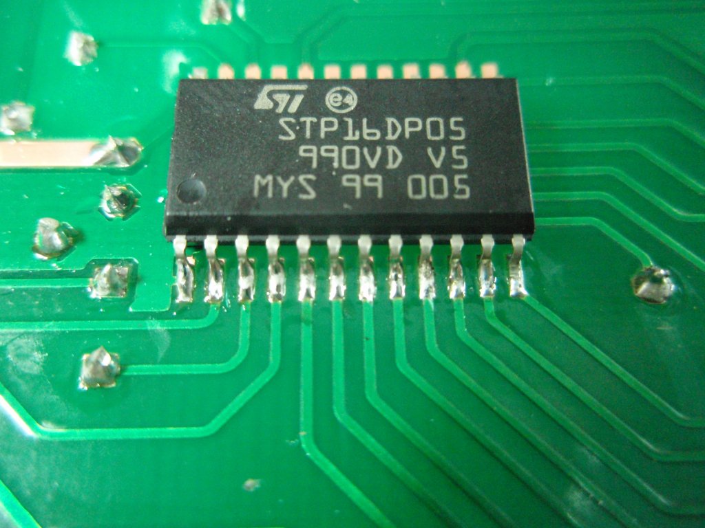
Fig. 20 / 21 These
two photos show both driver IC's soldered to the PCB. This
is the quality of soldering you should be looking to repeat
on your own board.
Fig.22
Fig. 22 Once both
ICs have been soldered in to place you should give the
copper side of the board a thorough visual inspection to
check for solder bridges between pads and tracks.
Install PCB standoff or
spacers into the four mounting holes at the corners of the
PCB. These should provide enough clearance to ensure the
board isn't resting on the two Surface Mount ICs.
If you haven't already done
so you should also install the
PIC16F688 into the IC1 socket making sure it
is fitted the correct way round. There is a small
indent in the IC body at one end. Fit into the socket
so this is towards the edge if the board.
Power Supply
WARNING: You must use a 5 volt regulated power supply.
Connect a 5 volt, 1.0 amp
power supply to the DC power input jack J1. The DC
jack requires a centre
+ve input connection.
The power supply should be rated for 1 amp or greater, i.e.
1.5 amp would also be fine to use but 0.5 amp isn't.
The power LED1 should light. Measure
the voltage between pins 1 and 14 of IC1 again to ensure
there is 5 volts present.
As there is no reverse polarity protection on the board you
must ensure the power supply connector is correctly wired or
you will damage and destroy the LED driver IC's and other
parts.
If you apply a higher
voltage to the board you will destroy the PIC and driver
ICs. While the PIC is easy to swap out, removing the
two surface mount ICs will be very difficult and likely to
result in damage to the PCB.
It takes me about 01h30m to
assemble the LEDs in a cube and that doesn't include
assembly of the main PCB so you'll want to allow yourself
plenty of time. Patience is your friend on this one.
IMPORTANT
When the LED cube is installed onto the circuit
board DO NOT attempt to solder or
repair connections within the LED cube while the
board has power applied. ALWAYS disconnect the power before working on the LED cube.
If you
accidentally short an anode/cathode with power
applied there is a high probability that it will
destroy a LED driver output in IC2/3.
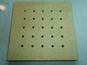
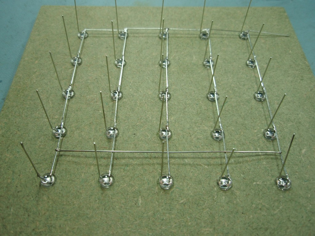
To assemble the LEDs
into a cube you will need to make a simple jig
using a piece of MDF or similar material (see photo
right). You can download a PDF template for the jig
here.
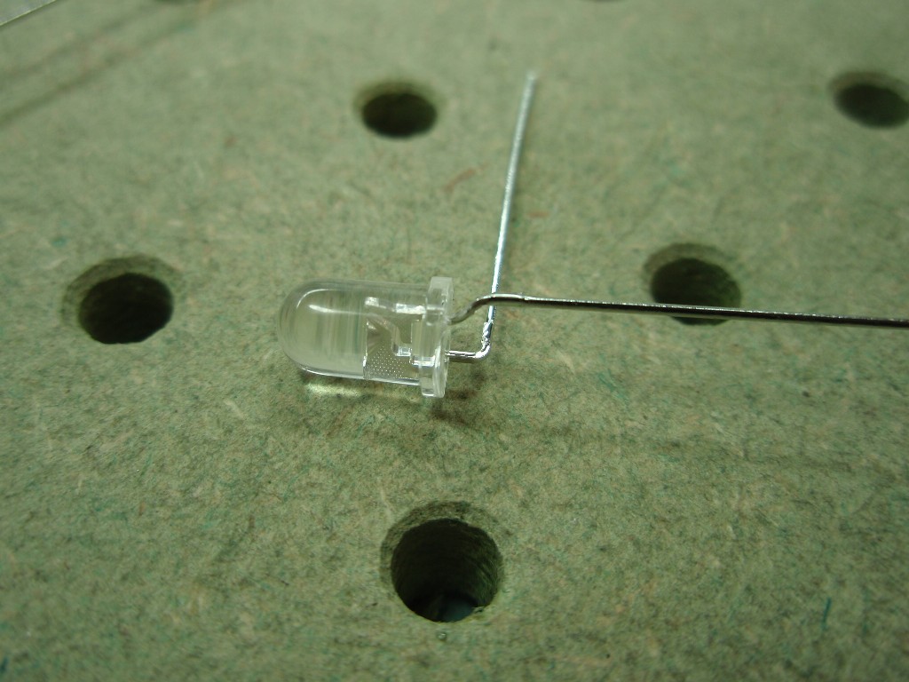
Fig 1. Carefully
bend the leads on each LED as shown. The LED cathode should
be cranked out so it is aligned with the side of the LED
package. This is more important with 5mm LEDs than 3mm
LEDs which have a much narrower package. The anode should be bent to an angle of 90o.
Take care bending the leads to avoid stressing them as they
enter the LED body.
I get many emails telling me the LED shown in the photo in
fig 1. has the cathode and anode leads the wrong way round
because of the shape of the lead inside the LED body; they
are not.
The fig 1. photo should
only be used as a reference for forming the leads, not to
identify the cathode/anode terminals. With the
vast numbers of cheap LEDs available from the Far East there
is no 'standard' way of identifying the cathode and anode
leads on the LED.
DO NOT make any assumptions
based on:
the shape of the leads
inside the LED body
the flat on the side
of the LED body
the length of the
leads.
Normally the shorter lead
is the cathode but you should verify this before assembling
the cube.
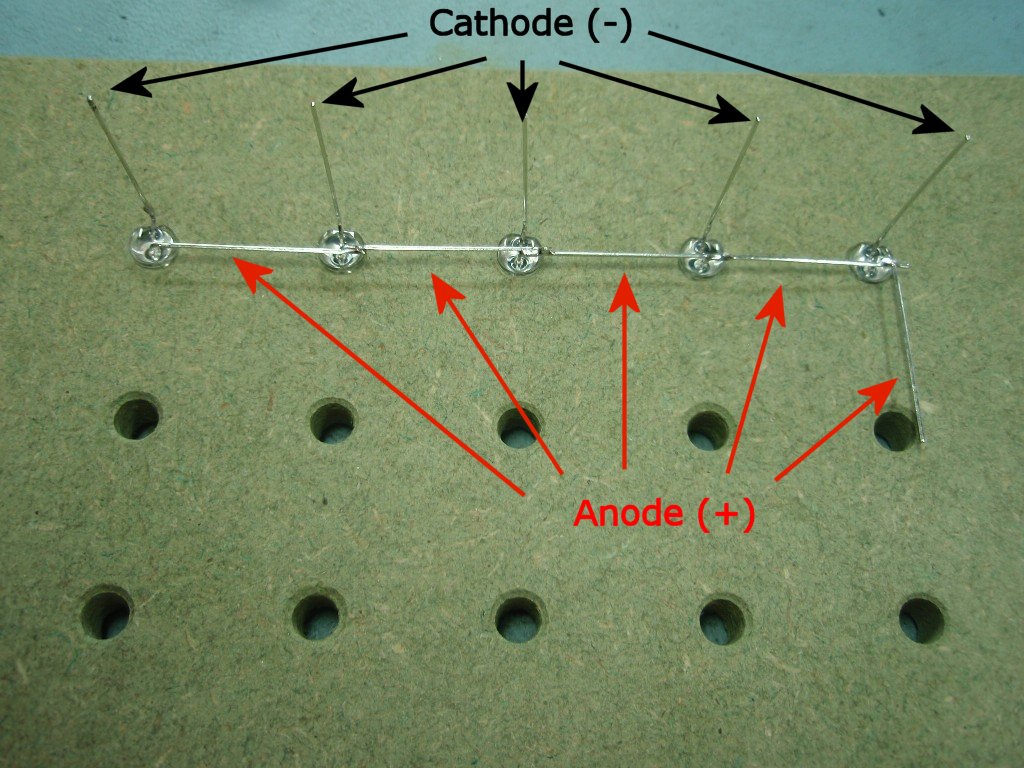
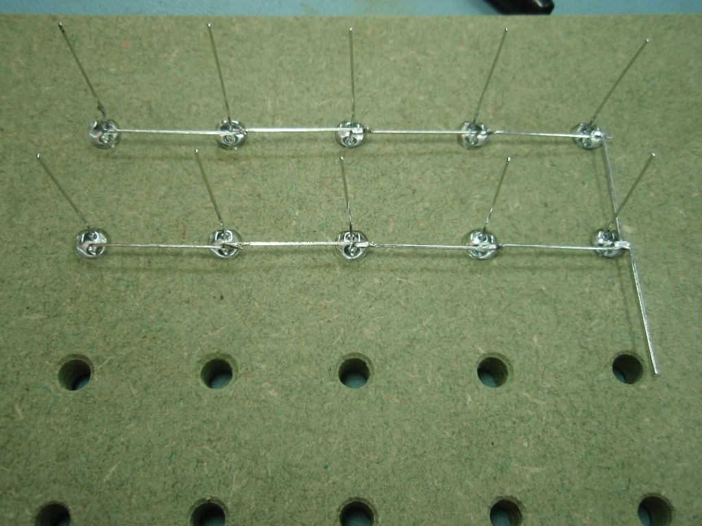
Fig 2. The LED
anodes run horizontally around the jig and are connected
together. The LED cathodes are perpendicular to the jig.
Install five LEDs into one row of holes as shown. The last
LED should have its anode lead bent round so it connects
with the LED in the next row. Solder the anode of each LED
to the next LED.
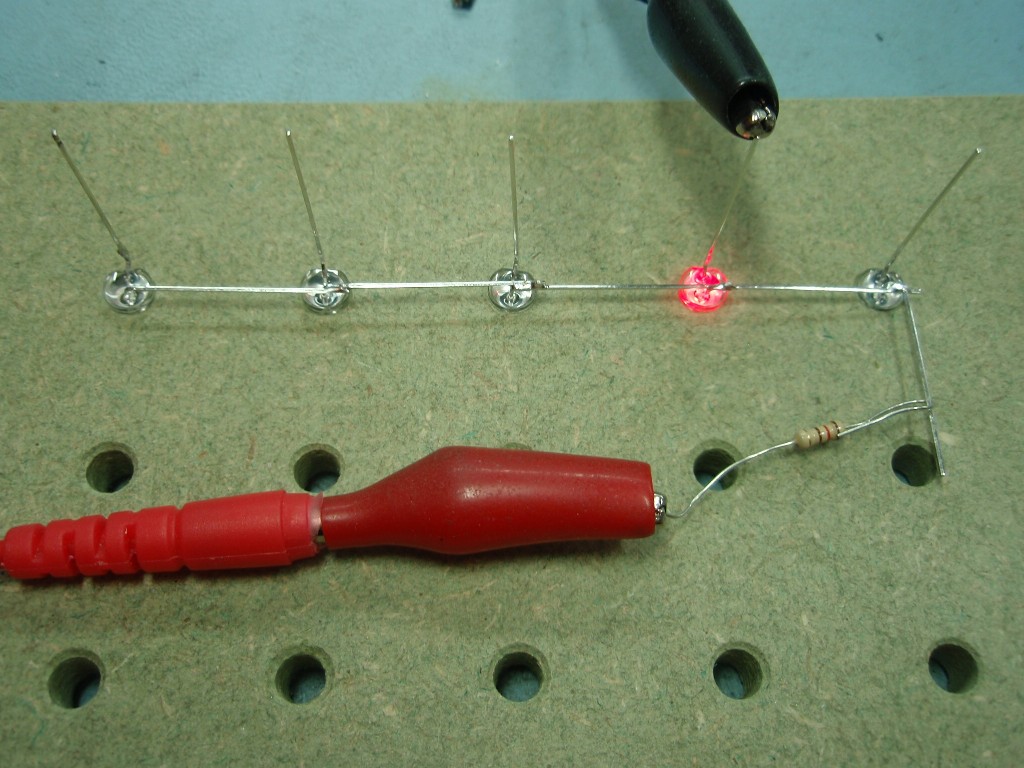
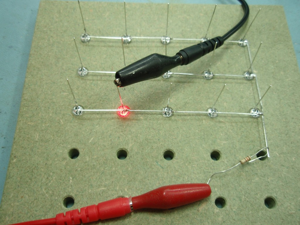
Fig 3. Using a 5
volt power supply and resistor (anything from 120 to 330
ohms will work), test each LED to make sure it is not faulty
or installed with anode/cathode terminals reversed. With a
125 LEDs to assemble getting one the wrong way round as the
tedium sets in is quite likely!
WARNING. If you skip this test and get the
LEDs assembled into the cube then find an LED isn't working
it will be extremely difficult to correct it.
IMPORTANT:
Only do this test while the LEDs are on the jig.
DO NOT attempt to do this testing with the LEDs
installed on the circuit board as it may cause
damage to the other components.
Fig.4
Fig .5
Fig. 6
Fig 4. Install LEDs
into the next row and solder their anodes together.
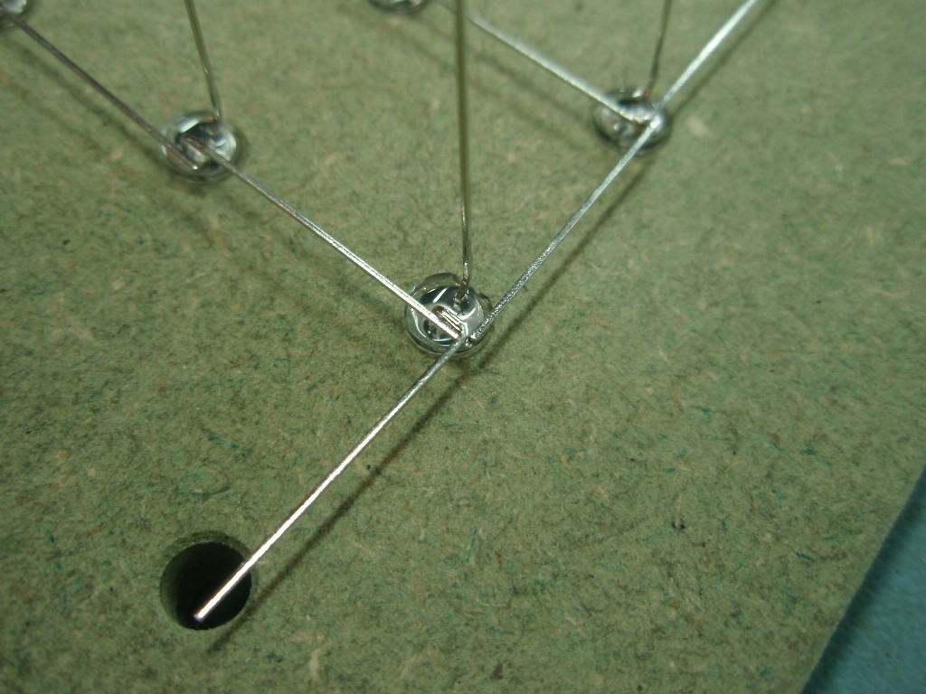
Fig 5/6. Connect the
anode terminal of the right most LED to the LED in the next
row. You will also have the anode lead from the LED to the
left meeting at this point. Solder all three leads together
as shown making sure the lead from the LED on the previous
row clears the vertical cathode lead.
Fig.7
Fig
.8
Fig. 9
Fig 7. Continue to
install LEDs in to each of the rows, soldering and testing
as you go.
Fig 8. With all five
rows completed solder a wire across all the rows to hold
the layer in shape. This wire also serves as an electrical
connection. Note how the wire goes over-and-under the LED
anode leads.
Carefully remove the
assembled layer from the jig and put to one side. Repeat the previous steps
for each of the five layers.
Fig.10
Fig .11
Fig. 12 (1280 x 960
resolution)
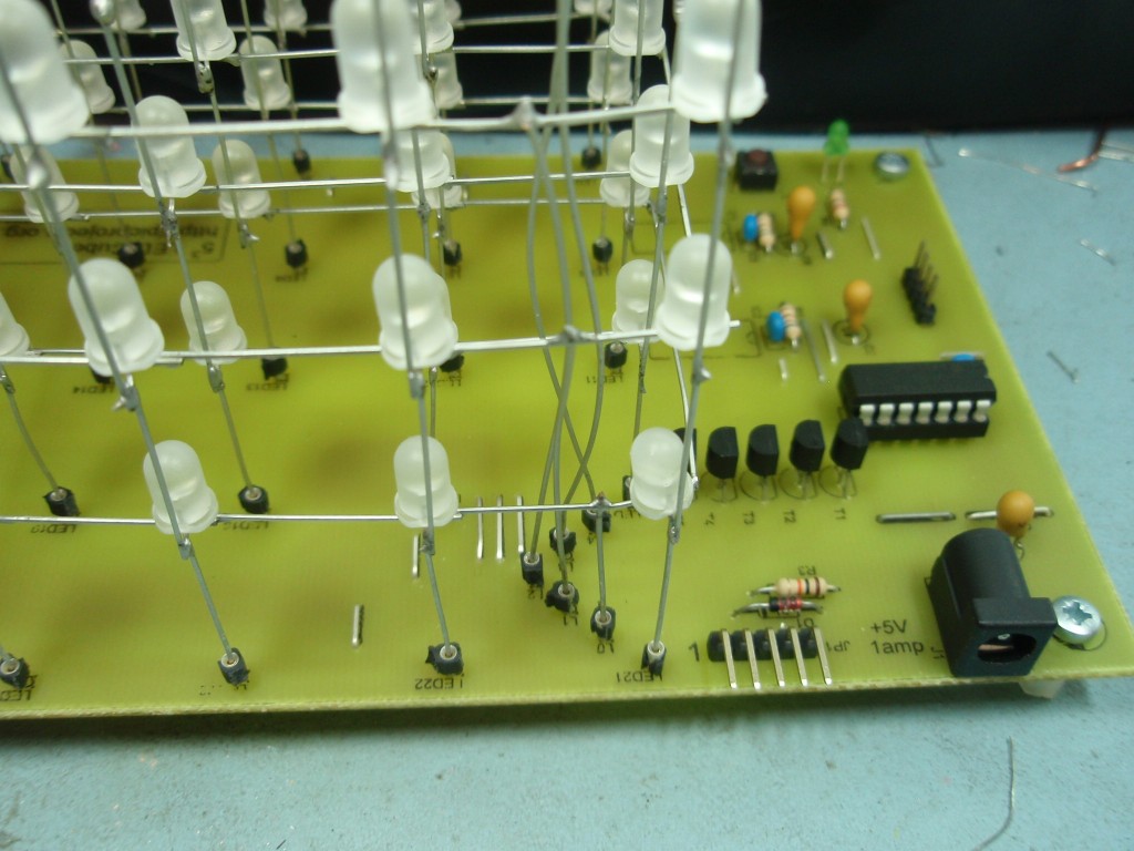
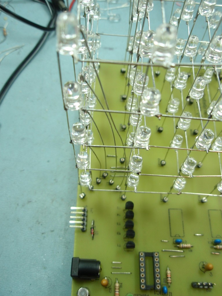
Fig 9-12. These
pictures show the general arrangement of the LED cube.
Assemble the cube by
inserting the cathode leads of the first LED layer into the
sockets on the PCB.
Next attach the second
layer to the first. The best way to do this is lie the PCB
on its side. Solder the four corner LEDs of the second
layer to the first layer.
With the four corners
soldered, put the PCB flat on the work surface. Next work
around the outside of the cube soldering the two layers
together. Then work your way in to the middle of the cube
soldering each LED to the one below. It's a bit fiddly
getting into the middle of the cube but not impossible.
I strongly advise that
you do not solder the bottom LEDs into the sockets on the
PCB. The reason for using the sockets is to make it
easy to remove the LEDs from the PCB if you need to repair
it.
All the time keep looking
across the LEDs from several directions to ensure the LEDs
in the upper layer are level and aligned with those in the
layer below; make any adjustments as needed. If you don't
keep the layers level as you go the whole cube will be
distorted by the time you get to the very top layer.
Repeat this until all five
layers are connected together to form the cube.
Fig.13
Fig 13. Once all the
layers are in place attach the five wires to the layer drive
sockets as shown in the photo. Ensure the wires do not
short on each other as they rise up through the cube. The
sockets are spaced apart on the PCB to help with this.
The connections are labelled L1 to L5, L1 being the
lowest layer, L5 being the top.
Once
the cube is installed on the PCB and all connections
have been made, take a good look over the cube
assembly to make sure no leads have got bent and are
now shorting out against one another.
Failure to do this is a sure way to damage the LED
driver ICs.
Several
hundred LED cube kits have been sold now and very
few customers have problems with them. However
in a handful of cases there is a common problem;
that is one or both LED drivers (IC2/3) have a
failed output(s).
The most probable
cause for this is that at some point there has been
a short circuit between the column and layer drive
wires somewhere in the cube while it was powered on.
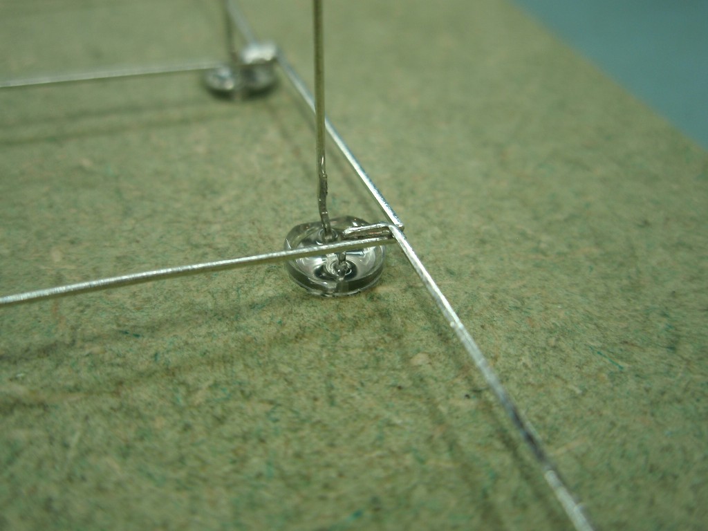
When assembling the
layers into a cube and also when attaching the LED
cube assembly to the PCB it is easy for a short to
occur since the clearance between the wires is very
small where the LEDs interconnect (see photo below)
Therefore it is
essential to:
Take care
during assembly; the cube is easily deformed so
be very gentle with it.
Do not attempt
to solder, tweak the wires or touch the cube
assembly when it is powered on - ever.
Before
powering up for the first time check, check and
check again for wires that are shorting
together. If you don't find them now, they will
show themselves up once you apply power and then
it will be too late!
If the output of
the driver IC does get shorted directly to the layer
wiring it is likely to be damaged faster than you
can blink so even the briefest accidental short will
most likely damage it.
If
you bought a LED Cube kit from Picprojects and
you do find you have damaged the LED driver IC contact
us and we will replace one pair of LED
drivers IC's F.O.C. (free-of-charge) one time only -
can't say fairer than that.
When
all the LEDs in a column remain on all the time it
indicates that either:
There is a
short to ground on that column connection -
unlikely
the output
from the LED driver IC connected to that
column has failed short-circuit.
If none of the LEDs
in a single column light it indicates that either
the output from the LED driver IC is:
not connected
to the column - wiring fault
there is a
short circuit between the column and one or more
of the layer drive wires
the output
from the LED driver as failed open
circuit
If only LEDs in the
lower part of a column light but not the ones above.
Generally
indicates the cathode lead has not been soldered
to the LED below.
To construct the cube with
3mm LEDs a second template was printed and then fixed to the
5mm jig with an offset. This was then drilled with 3mm
holes to make a single jig that can be used for assembling
both 3mm and 5mm cubes. In practice the body of most 3mm
LEDs seems to be about 2.9mm or less so the LED sits a bit
lose in 3mm hole. You might want to drill at 2.5mm and ream
the holes out, frankly I couldn't be bothered but it is
easier to solder it altogether if the LED body is held by
the jig.
5mm Cube
with green LEDs This video shows the original prototype of the cube built
on some
prototyping board and running an early version of the code.
Hundreds of
LED cube kits have been sold and very few people contact me
with problems. However, it is quite a technical kit to
assemble and the surface mount driver chips (IC2/3) can be
tricky to solder. The information in this section is
put together from issues that have come to my attention from
end users.
To help troubleshoot
problems I've added a diagnostic function to the LED cube firmware.
All firmware versions from 1.0.3 (filename LEDcubeC2.hex)
will contain this feature. Any kit or
pre-programmed chip sold after 31-09-2010 has this code. The diagnostic
routine changes the signals between the PIC and the
two driver ICs very slowly. This allows checking of the
signals to see that they are present at all the correct pins of the ICs using
a simple LED and resistor as a test probe.
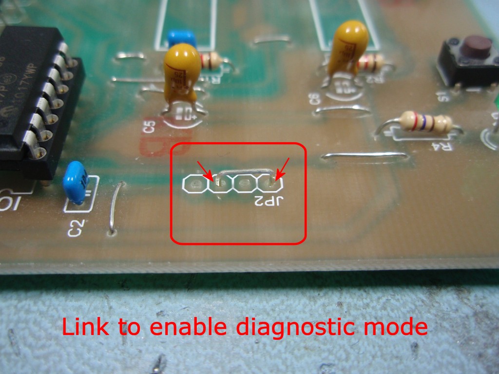
Enabling Diagnostic Mode
The
diagnostic mode is enabled by grounding pin 2 (RA5)
of IC1. Since the pin is brought out on the
JP2 header the easiest way to ground the input is to fit a
jumper wire as shown in the photo (right).
When the board is
powered up, if the jumper is present the firmware
will run the diagnostic code. This first
clears the shift registers in driver chips
IC2/3 so no LEDs should be on. It then clocks a
high level in to the first
shift register (IC2) which lights LED 25.
Clock and latch signals are then generated at about
2Hz and the LED 'walks' from LED25 to LED1, when it
reaches LED1, it goes back to LED25, at the same
time switching to the next layer up. When it
reaches LED1 in layer five it goes back to LED25 in
layer one and repeats.
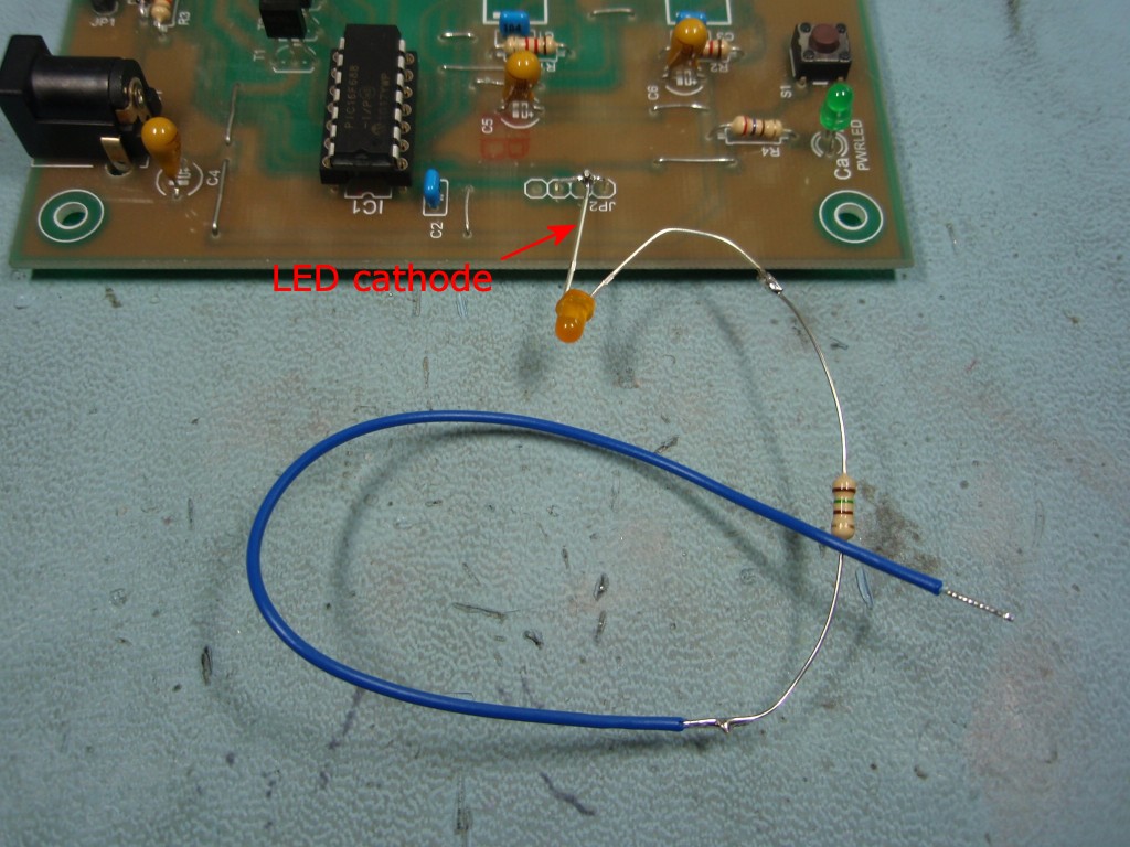
Simple Test Probe
The
presence of the signals can be checked using a
simple LED and resistor as shown in the photo.
With the diagnostic jumper fitted a good place to
attach the LED cathode is directly on the jumper
since this connects to ground.
A spare LED from the
cube can be used but any LED will do. For the
resistor use any value from 150R up to about 1K0.
Video
showing diagnostic mode running
#1 cause of
failed LED driver ICs is shorting out the two terminals of
an LED in the cube. This can happen when fitting the cube to
the PCB, while making final adjustments to the shape of the
cube while it's running, or trying to solder the LEDs while
it's running.
If a
column of LEDs stays ONwhen the
cube is running, (in diagnostic mode a single LED) then
either there is a short to ground on that signal or the
more likely cause is that the output from the driver IC
has failed so it is permanently turned on. In this
case the driver IC will need replacing.
If a
column of LEDs stays OFF when the
cube is running, (in diagnostic mode a single LED) then
either there is a break in the track to that LED column
or the output from the driver IC has failed so it is
permanently turned off. In this case the driver IC
will need replacing.
If you connected a power supply with the wrong
voltage it is possible that all the LEDs in a column
have been destroyed. In this case you need to
remove the LED cube from the PCB and test the LEDs out
of circuit.
If you think you have a failed driver IC contact
Picprojects by email for assistance.
LED
Columns 25-10 are driven by LED driver IC2
LED Columns 9-1 are driven by LED driver IC3
If LEDs
25-10 or 9-1 are either all on or all off then the
likely cause is a broken connection on either the SIN, CLK or LATCH signals between the PIC and the driver ICs
or the two driver ICs themselves. This should be
easy to locate using the diagnostic mode.
If just a
single LED in the cube stays off all the time then it's
likely to be either a failed LED, LED not soldered to
the rest of the cube or LED installed with the
cathode/anode wrong way round (you did test for this
during assembly of the cube didn't you?)
If you connected a power supply with the wrong
voltage it is possible that the LED has been
destroyed. In this case you need to remove the LED
cube from the PCB and test the LEDs out of circuit.
Common
cause of breaks in the track is mentioned in the
construction section. When link wires or excess
leads are trimmed during assembly, twisting the side
cutters or pulling up on them as the cut is made can
break the copper track at the edge of the solder joint.
To repair it just scrape back 3mm of solder resist and
bridge with solder.
These notes apply to the
latest firmware version, ledcubeC3.HEX released
15/01/2011
The LED cube runs as a
standalone device.
The latest firmware can
operate in one of two modes:
By default it will run the
animation sequences in random order.
Pressing and holding switch
S1 as the LED cube is powered on selects the sequential
mode. The animations are run sequentially in a
continuous loop.
In either mode immediately
after power-on the LED Cube displays the
text 'PICPROJECTS' followed by the firmware version
(currently C3) before continuing in the selected mode.
To modify or develop your
own animation effects you will need to modify the source
code, reassemble it and reprogram the PIC using a separate
PIC programmer. Details for the drawing processor can
be found here
Changing the startup
text display
If you want to personalise
the text that it displays at startup, here's how.
You will need:
The free MPLAB IDE
software installed on your computer. A
short guide to downloading and using MPLAB can be
found here.
A PIC Programmer
hardware device e.g. Microchip PICkit2
Download the ledCubeC.zip
file from the firmware section below
and put all the files into a directory on your computer.
Open the files ledCubeC.asm
and CubeProgramJAN11.inc
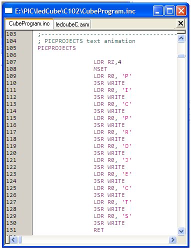
Find the section in the
CubeProgramJAN11.inc file shown in the screen dump right.
Each character is animated
using two instructions, for example the letter 'P' is done
using these two instructions.
LDR R0,
'P'
JSR WRITE
To change the text simply
edit the file, changing the characters; you can add or
remove the LDR/JSR instruction pairs if you need more or
less characters.
In the example above the
text 'HELLO' will be animated at start-up instead of 'PICPROJECTS'
Once the CubeProgramJAN11.inc
file has been modified save it. Then select the
ledcubeC.asm file and reassemble it. The resulting
ledcubeC.HEX file will then need to be programmed into the
PIC.
You can go back to the
original code at anytime by downloading the ledcubeC.HEX
file and re-programming the PIC.
The code has now been
updated to work with the enhanced midrange PIC16F1824 and
16F1825.
The original version of code for the the PIC16F688 is still
available. The two versions are functionally identical.
The 16F688 and 16F1824 run the same animation sequences.
There are six additional animation sequences in the code for
the 16F1825 as it has an extra 4K of program memory.
The HEX files for
16F688, 16F1824 and 16F1825 are ready to
program directly into a PIC. The zip file contains
the source code which you can modify or just view to see how
it works. If you are going to modify the code I recommend
you download and install the
Microchip MPLAB IDE which will allow you to edit, modify
and program the PIC seamlessly.
Not got a PIC programmer? Buy a
pre-programmed PIC from the
on-line shop
This
is the latest firmware released on 15-01-2011,
ledcubeC3.HEX, v1.0.4
Features new to this version:
improved random sequence selection
two operating modes; random or sequential
5
new animation effects for a total of 28 effects.
Jozef Blahút from Slovakia
has been busy creating some new animations effects as well
as modifying some of the Picprojects ones. He's made a
really good job and I've been impressed enough with them to
ask his permission to make them available here.
Because of the memory
limitations on the PIC16F688 we can't included all the
original animations as well as the new ones created by Jozef.
Therefore I've provided an alternative HEX download that
includes all the animations created by Jozef while losing a
few of the original Picprojects ones. In addition to
this you can download a ZIP file that contains the new
animation effects in separate .TXT files. These can be cut
and pasted into a new include file and reassembled to create
your own custom mix of animations effects.
If you need a PIC
Programmer I strongly recommend the
Microchip PICKit
2, this is available from suppliers world wide or direct
from Microchip. It's reasonably cheap to buy and reliable.