|
53
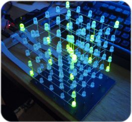
LED CUBE Controller
for PIC16F688
|
 |
Controlling the LED Cube Display
The problem with using a data
lookup table to drive the LED cube is the amount of data needed.
If the data is packed it requires 16 bytes to hold the state of the
cube (125 / 8 = 15.625). Since the 16F688 PIC only has 4K
words of program memory and the main code uses ~1455 words that only
leaves about 2600 words for table data. This in turn is
room for only 168
complete cube states to be held in memory so if you wanted the text
'PICPROJECTS' to be displayed, shifting from the back to the front
of the cube it would require 16 bytes x 5 frames per letter x 11
letters = 880 bytes.
Clearly the table lookup method
isn't going to allow you to do very much before program memory runs
out. To get round this, the cube is controlled using a macro
command language that controls a virtual drawing processor.
Using code written with the macro commands defined for the cube
drawing processor the same animation can be done in 60 bytes.
(See example code dpcode.txt)
The instructions are implemented
using assembler Macros, for this reason the instruction mnemonics
have to be different to the PIC instruction set and MPASM assembler
reserved words. The instruction Macro names and register names
are uppercase and case sensitive. The Macro instructions are
converted into either one or two PIC assembler retlw
instructions at assembly time. When the PIC ledcube firmware
runs it reads these back as table data, decodes the instruction
based on bit-fields and then calls assembler functions to perform
the required drawing processor operation.
The Drawing Processor has 72
instruction, 8 registers, and a 33 level user stack. The
instruction set is similar to PIC assembler and you will need to
have knowledge of PIC assembly language programming and the Microchip MPASM / MPLAB
IDE if you intend to write your own routines using it. Also an
understanding of postfix stack operation wouldn't hurt.
Since the DP code is generated from
MPASM macros and just ends up being assembled with the rest of the
PIC program code, all the usual MPASM operators and number formats
are available to use when writing code for the DP.
Demo Code
The pre-assembled HEX file for the
LED cube projects contains some demo animation sequences. The
Drawing Processor code for this is contained in the file
CubeProgram.inc
Overview
In the context of this project, a
Voxel is a single LED within the cube whose position is defined by
its X,Y & Z coordinates.
Registers
The DP has 8 registers; 4 general
purpose and 4 special purpose. All registers are 8 bits wide and can
hold a value in the range 0-255. However, instructions that
use values in the special function registers expect the value to be
within the range shown in the table below. Values outside this
range may result in unpredictable code execution.
| Register name |
Function |
Range |
| R0 |
General purpose register
|
0-255 |
| R1 |
General purpose register
|
0-255 |
| R2 |
General purpose register
|
0-255 |
| R3 |
General purpose register
|
0-255 |
| RHOLD |
Hold time value for SHOW
command ( x 10mS) |
0-255 |
| RX |
X co-ordinate for voxel
and drawing functions |
0-4 |
| RY |
Y co-ordinate for voxel
and drawing functions |
0-4 |
| RZ |
Z co-ordinate for voxel
and drawing functions |
0-4 |
Timer
There is a single user timer that
counts from a preloaded value down to zero in 1 second intervals.
Stacks
The DP has two stacks, a user stack
and a return address stack. The return address stack holds the return
address for Jump to Subroutine (JSR) instructions and is not directly
accessible. The user stack is 33 levels deep and can be used
to push/pull any user register. It is also used to perform
math and logical operations by pushing the values on to the stack,
then executing the operation, the result being pushed back onto the
stack. To that end DUP, DROP, SWAP, OVER and ROT stack
operators are also implemented. This is a similar to the FORTH
programming language and not by coincidence:-).
- The user stack pointer has
wrap around capability so unmatched push/pull operations won't
overwrite memory outside the stack
This is important as the ADD/SUB/OR/AND/XOR operators always
push the result of the operation onto the stack. This means you
don't have to pull the result unless you need it, but you should
remember it is on the stack if you have something else pushed on
the stack previously. See also DROP instruction which discards
the entry on the top-of-stack.
- The user stack can hold a
maximum of 33 entries.
- Be aware that the PUSHXYZ and
PULLXYZ instructions use 3 stack entries.
- The return address stack does not
wrap and has no over/under
flow checking.
- The return address stack can hold up
to 8 return addresses.
Flags
- Fcarry - Set if carry occurred
during add instruction, cleared if no borrow occurred during
subtract (same as underlying PIC operations)
- Fzero - Set if result was
zero, cleared if result was non-zero. Fzero flag is also
modified by TSTVOX, CMP, Timer and external switch instructions.
Instruction Set
r - register name
k - literal, constant data or label
| Mnemonic |
Description |
Flags |
Register |
| NOOP |
No operation |
|
|
| |
|
|
|
| MSET |
Modify operations will set
voxel to on |
|
|
| MCLR |
Modify operations will set
voxel to off |
|
|
| MINV |
Modify operations will
invert current voxel value |
|
|
| |
|
|
|
| SETALL |
Turn on all voxels in cube
(independant of MSET, MCLR and MINV instructions) |
|
|
| CLRALL |
Turn off all voxels in
cube (independant of MSET, MCLR and MINV instructions) |
|
|
| INVALL |
Invert all voxels in cube
(independant of MSET, MCLR and MINV instructions) |
|
|
| |
|
|
|
| SHOW |
Transfer drawing buffer to
display and load value in RHOLD register into hold timer |
|
|
| |
|
|
|
| VOX k,k,k |
Load RX, RY, RZ and modify
voxel [ 0 <= k <= 4 ] |
|
RX,RY,RZ |
| VOXM |
Modify voxel at current
RX, RY, RZ co-ordinates |
|
|
| TSTVOX |
Test voxel at current RX, RY, RZ co-ordinates.
Fzero clear if voxel on : Fzero set if voxel off |
Fzero |
|
| |
|
|
|
| CHYR r |
Draw ASCII character
specified in register r in the Y (vertical) plane |
|
|
| CHZR r |
Draw ASCII character
specified in register r in the Z (horizontal) plane |
|
|
| CHY k |
Draw ASCII character value
k in the Y (vertical) plane [32 <= k <= 95] |
|
|
| CHZ k |
Draw ASCII character value
k in the Z (horizontal) plane [32 <= k <= 95] |
|
|
| |
|
|
|
| LINE k,k,k,k |
Modify a line of voxels,
specify x inc, y inc, z inc, length |
|
RX,RY,RZ |
| LINEX |
Modify line of voxels
across the whole X axis, located at RY,RZ |
|
|
| LINEY |
Modify line of voxels
across the whole Y axis, located at RX,RZ |
|
|
| LINEZ |
Modify line of voxels
across the whole Z axis, located at RX,RY |
|
|
| |
|
|
|
| PLANEX |
Modify all voxels in the YZ plane, located in the X-axis at RX |
|
|
| PLANEY |
Modify all voxels in the XZ plane, located in the Y-axis at RY |
|
|
| PLANEZ |
Modify all voxels in the XY plane, located in the Z-axis at RZ |
|
|
| |
|
|
|
| ROTATEX |
Rotate entire cube along a
line at y=2, z=2 in the x-axis |
|
|
| |
|
|
|
| SHXL |
Shift entire drawing
buffer left one voxel. |
|
|
| SHXR |
Shift entire drawing
buffer right one voxel. |
|
|
| SHYU |
Shift entire drawing
buffer up one voxel |
|
|
| SHYD |
Shift entire drawing
buffer down one voxel |
|
|
| SHZF |
Shift entire drawing
buffer forward one voxel |
|
|
| SHZB |
Shift entire drawing
buffer back one voxel |
|
|
| |
|
|
|
| DECX |
Decrement RX register,
modulo 5 |
Fzero |
RX |
| DECY |
Decrement RY register,
modulo 5 |
Fzero |
RY |
| DECZ |
Decrement RZ register,
modulo 5 |
Fzero |
RZ |
| INCX |
Increment RX register,
modulo 5 |
Fzero |
RX |
| INCY |
Increment RY register,
modulo 5 |
Fzero |
RY |
| INCZ |
Increment RZ register,
modulo 5 |
Fzero |
RZ |
| |
|
|
|
| DECR r |
Decrement register, modulo
256 |
Fzero |
r |
| DECRSZ r |
Decrement register, modulo
256, Skip next instruction if result is zero |
|
r |
| INCR r |
Increment register, modulo
256 |
Fzero |
r |
| INCRSZ r |
Increment register, modulo
256, Skip next instruction if result is zero |
|
r |
| |
|
|
|
| PUSHR r |
Push register contents
onto top of stack |
|
|
| PULLR r |
Pull top of stack and
place contents into register |
|
r |
|
PUSHXYZ |
Push registers
RX, RY, RZ on to stack |
|
|
|
PULLXYZ |
Pull registers
RX, RY, RZ from stack |
|
RX,RY,RZ |
|
DROP |
Pull entry
from top of stack and discard it ( a -- ) |
|
|
|
SWAP |
Swap top two
entries on stack. ( a b -- b a ) |
|
|
|
DUP |
Duplicate
entry on top of stack. (a b -- a a b ) |
|
|
| OVER |
Operates on the stack : (a
b -- a b a ) |
|
|
| ROT |
Operates on the stack : (
a b c -- b c a) |
|
|
| TSTZ |
Test value on top of stack
and condition Fzero flag (a -- a ) : a==0 Fzero set, a
!= 0 Fzero clear |
Fzero |
|
| |
|
|
|
| ADD |
pulls two values from the
stack, adds them together and pushes result back onto stack |
Fzero
Fcarry |
|
| SUB |
pulls two values from the
stack, subtracts them and pushes result back onto stack
order is (TopOfStack-1) - (TopOfStack) -> TopOfStack |
Fzero
Fcarry |
|
| AND |
pulls two values from the
stack, performs a bitwise 'AND' result is pushed back onto
stack |
Fzero |
|
| OR |
pulls two values from the
stack, performs a bitwise 'OR' result is pushed back onto
stack |
Fzero |
|
| XOR |
pulls two values from the
stack, performs a bitwise 'XOR' result is pushed back onto
stack |
Fzero |
|
| NOT |
pull value from top of
stack, perform bitwise 'NOT' operation on byte and push
result back on to stack |
Fzero |
|
| |
|
|
|
| CMP r, k |
Compare register contents
with k. If contents of r == k then Fzero Set, else
Fzero Cleared. |
Fzero |
|
| |
|
|
|
| LDXYZ k,k,k |
Load RX, RY, RZ
[ 0 <= k <= 4 ] (see also
VOX k,k,k) |
|
RX,RY,RZ |
| LDR r,k |
Load register with value k
[0 <= k <= 255 ] |
|
r |
| LDRAND r,k |
Load register with random
number in the range [ 0 <= Random Number < k ] |
|
r |
| LDTMR k |
Load timer with period in
seconds [1 <= k <= 255 ] |
|
|
| ADDTRND k |
Add random
number in the range [ 0 <= Random Number < k ] to
contents of Timer |
|
|
| |
|
|
|
| SKIPZ |
Skip next instruction if
Fzero flag is set |
|
|
| SKIPNZ |
Skip next instruction if
Fzero flag is clear |
|
|
| SKIPC |
Skip next instruction if
Fcarry flag is set |
|
|
| SKIPNC |
Skip next instruction if
Fcarry flag is clear |
|
|
| SKIPTOUT |
Skip next instruction if
Timer == 0 |
|
|
| JUMP k |
Jump to program address k |
|
|
| JSR k |
Jump to subroutine at
address k |
|
|
| RET |
Return from subroutine |
|
|
| |
|
|
|
| RANDSEED |
Seed random number
generator with non-zero value from TMR0 |
|
|
| SYNCEXT k |
Wait for a falling edge on
SW1 input before continuing program execution or timer out |
Fzero |
|
| TSTSW |
Test SW1 input. Set Fzero
flag if switch active (pressed), Clear Fzero flag if switch
not active |
Fzero |
|
Instruction details
SHOW
All drawing instructions operate on
the drawing buffer. This allows a new image to be built up in
the drawing buffer while the LED cube displays the contents of the
display buffer. To transfer the drawing buffer into the
display buffer you must use the SHOW instruction. When the
show instruction is executed it will wait for the previous hold
delay to complete if it is still active. It then sets the buffer
transfer flag and waits for the display driver to copy the drawing
buffer into the display buffer and clear the transfer flag. At
this time the value in RHOLD is transferred into the hold timer and
the instruction exits. RHOLD timer is period to wait x
10mS. If RHOLD is 0, the buffer is transferred at
the next cube display refresh.
This command is blocking, program
execution will not continue until the current hold timer has timed
out and the interrupt display driver has transferred the buffer.
MSET, MCLR, MINV instructions
control the operation of VOX, PUT, LINE and PLANE instructions.
- MSET turns on voxels
- MCLR turns off voxels
- MINV inverts the current voxel
state
The operating mode remains in
effect until changed by another instruction.
VOX RX, RY, RZ / VOXM / TSTVOX instructions
operate on a single Voxel
The voxel is modified according to
current mode set by MSET / MCLR / MINV instruction.
- VOX RX, RY, RZ loads
co-ordinates into RX, RY, RZ and modifies the voxel
- VOXM modifies the voxels using
current RX, RY and RZ co-ordinates
- TSTVOX test the voxel at the
current RX,RY,RZ co-ordinates and then sets the Fzero flag.
Fzero flag is cleared if the voxel is on, Fzero is set if
the voxel is off
SETALL, CLRALL and INVALL
instructions operate on the entire cube
These instructions operate independently of the current Voxel mode set by the MSET, MCLR, MINV instructions.
Stack operations
Stack Notation:
( stack before -- stack after ) e.g. SWAP
( a b -- b a )
PUSHXYZ
( -- Z Y X)
PULLXYZ ( Z Y X --
)
These two instructions
push and pull the X,Y and Z registers to/from the user stack in a
single command. The order the registers are pushed onto the
stack is X-Y-Z, so the Z register is at the top-of-stack after a PUSHXYZ instruction.
PUSHR Rn ( -- Rn)
PULLR Rn ( Rn -- )
Push or pull the single register
to/from the top of the user stack
DROP ( a -- )
discards the top entry from the stack
SWAP
( a b -- b a )
swaps the top two values on the stack
DUP ( a --
a a )
duplicates the top entry onto the top of the stack
OVER (a b -- a b a )
inserts copy of the top stack entry behind the second entry
ROT ( a b
c -- b c a)
rotates the top three entries on the stack.
LDTMR, ADDTRND and SKIPTOUT
instructions control the operation of a user timer.
The timer is loaded with the number
of seconds required for the timer period. It then counts down
until it reaches zero and stops. The SKIPTOUT instruction
tests the current value in the timer and will skip the next
instruction when it reaches zero.
ADDTRND instruction adds a random value between
0 and k-1 to the value already in the timer. This allows the
timer to be loaded with a random value between any two values,
by using a LDTMR instruction followed by a ADDTRND instruction.
SYNCEXT
The sync external instruction waits
for a falling edge on the S1 input or a timeout before continuing
program execution.
If the timeout value is set to 0,
the instruction waits indefinitely for a falling edge before
continuing. If the timeout value is set between 1 and 255, the
instruction waits until either a falling edge is detected or the
timer reaches 0. The timer decrements at one second intervals
and is shared with the other timer instructions. The timer is
not cleared if the instruction exits on a falling edge.
The Fzero flag is set if the
instruction exits on a falling edge, and cleared if it exits on a
time out.
SYNCEXT 0
; wait indefinitely for falling edge on S1 input before
continuing
SYNCEXT 12 ; wait for 12 seconds, or
failing edge on S1 input before continuing
There is no software debouncing
implemented on this control input, it expects a clean logic level
signal.
TSTSW
The TSTSW instruction reads the
logic level on the switch input. If the logic level is low
(switch pressed) the Fzero flag is set, if the logic level is high
(switch not pressed) the Fzero flag is cleared. This
instruction is not blocking, the input is tested, the Fzero flag
conditioned and code execution continues.
DECRSZ and INCRSZ instructions
do not modify the Fzero flag.
DECR and INCR
instructions do modify the Fzero flag.
I appreciate this doesn't seem
logical but it reflects the way the underlying PIC instructions
work.
INCX, INCY, INCZ and DECX, DECY,
DECZ instructions do modify the Fzero flag. These
instructions use Modulo 5 for the increment/decrement so the number
increments from 4->0 and decrements from 0->4.
It is important to note that the
DECR, INCR, DECRSZ, INCRSZ can be used on all registers
including RX, RY, RZ. However, this can lead to a value in the
register that is outside the valid range of 0 =< Rxyz =< 4
since these instructions operate on the byte modulo 256.
Instructions that follow and operate on the values in the RX, RY ,
RZ registers may cause the underlying PIC firmware to crash if the
value is outside of the expected range.
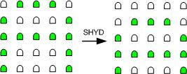
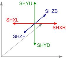
SHXL, SHXR, SHYU, SHYD, SHZF, SHZB
instructions shift the entire drawing buffer one voxel in the
direction specified. The voxels at the incoming edge of the
shift are cleared (set to off)
|
Example.
Shift down:
Before
After
|
 |
LINE x_inc, y_inc, z_inc, length
This instruction modifies a line of
voxels.
- x_inc, y_inc and z_inc can
have a value of -1, 0 or 1
- The start point for the
line is the current value in RX, RY, RZ
- After the voxel at
RX,RY,RZ has been modified:
RX = RX + x_inc : RY = RY + y_inc : RZ=
RZ + z_inc : Length = Length -1
This repeats until Length == 0
- The Line instruction will
leave
RX, RY and RZ values set to the finish point for the line.
This allows consecutive line instruction to draw a new line
starting from the end point of the previous line.
- The increment/decrement
operation on the registers are modulo 5 so the decrement
will roll under from 0 back to 4 and the increment rolls
over from 4 to 0
examples
MSET
LDXYZ 0,0,0
LINE 1, 1, 1, 5plots
a line through the following voxels
| RX |
RY |
RZ |
| 0 |
0 |
0 |
| 1 |
1 |
1 |
| 2 |
2 |
2 |
| 3 |
3 |
3 |
| 4 |
4 |
4 |
|
MSET
LDXYZ 0,4,2
LINE 0, -1, 1, 2
plots a line through the following voxels
|
MSET
LDXYZ 2,2,2
LINE -1, 0, 1, 4
plots a line through the following voxels
| RX |
RY |
RZ |
|
| 2 |
2 |
2 |
|
| 1 |
2 |
3 |
|
| 0 |
2 |
4 |
|
| 4 |
2 |
0 |
<- rollover
|
|
MSET
LDXYZ 0,0,0
LINE 0, 0, 1, 5plots
a line through the following voxels
| RX |
RY |
RZ |
| 0 |
0 |
0 |
| 0 |
0 |
1 |
| 0 |
0 |
2 |
| 0 |
0 |
3 |
| 0 |
0 |
4 |
|
| LINEX,
LINEY, LINEZ
These instructions draw a full length line across one axis in the drawing buffer.
The voxels in the line will
be set, cleared or inverted according to the current mode
set by the most recent MCLR, MSET or MINV instruction.
These three instructions
execute faster than using the LINE instruction. |
|
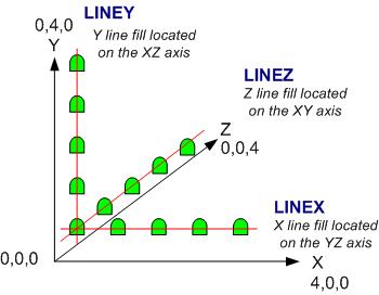
- LINEX
located in the Y-Z planes by the current values of RY
and RZ
- LINEY
located in the X-Z planes by the current values of RX
and RZ
- LINEZ
located in the X-Y planes by the current values of RX
and RY
- The RX, RY and RZ
register values are unchanged by these instructions.
|
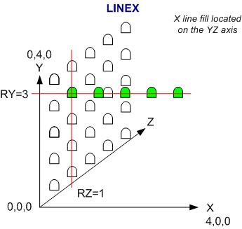
Example of LINEX.
Values in RY and RZ
registers locate the line in the YZ axis.
The value of RX register is ignored |
| PLANEX,
PLANEY, PLANEZ
The PLANE instructions fill an entire plane in the drawing
buffer.
The voxels in the plane
will be set, cleared or inverted according to the current
mode set by the most recent MCLR, MSET or MINV instruction. |
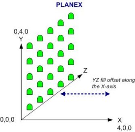
Value in RX specifies position
along the X-axis |
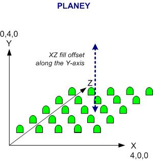
Value in RY specifies position
along the Y-axis |
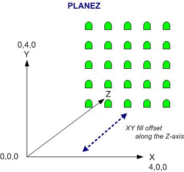
Value in RZ specifies position
along the Z-axis |
| CHZ, CHZR,
CHY, CHYR A 5x5
character set has been defined for the ASCII characters in
the range 32 to 95. This covers 0-9 and uppercase A-Z
along with most symbols.
The characters can be drawn
in the XY plane along the Z-axis or the XZ plane on the
Y-axis.
There is no support for drawing characters in the YZ plane.
|
| Character 'A' in the XY
plane value in RZ
positions character in the Z plane
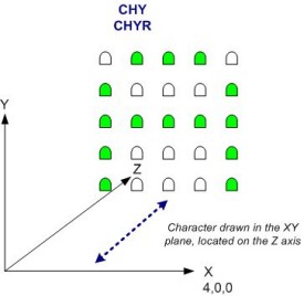
|
Character
'A' in the XZ plane
value in RY positions character in the
Y plane
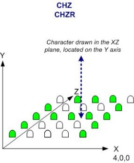 |
Given the way the PLANEY and
PLANEZ commands work you would expect CHY and CHZ commands to work
the opposite way round to the way they do and I wouldn't disagree
but if I change it now it breaks any code people may have already
written.
|