|
RGB LED
PWM Driver for
Description
Changes for R3
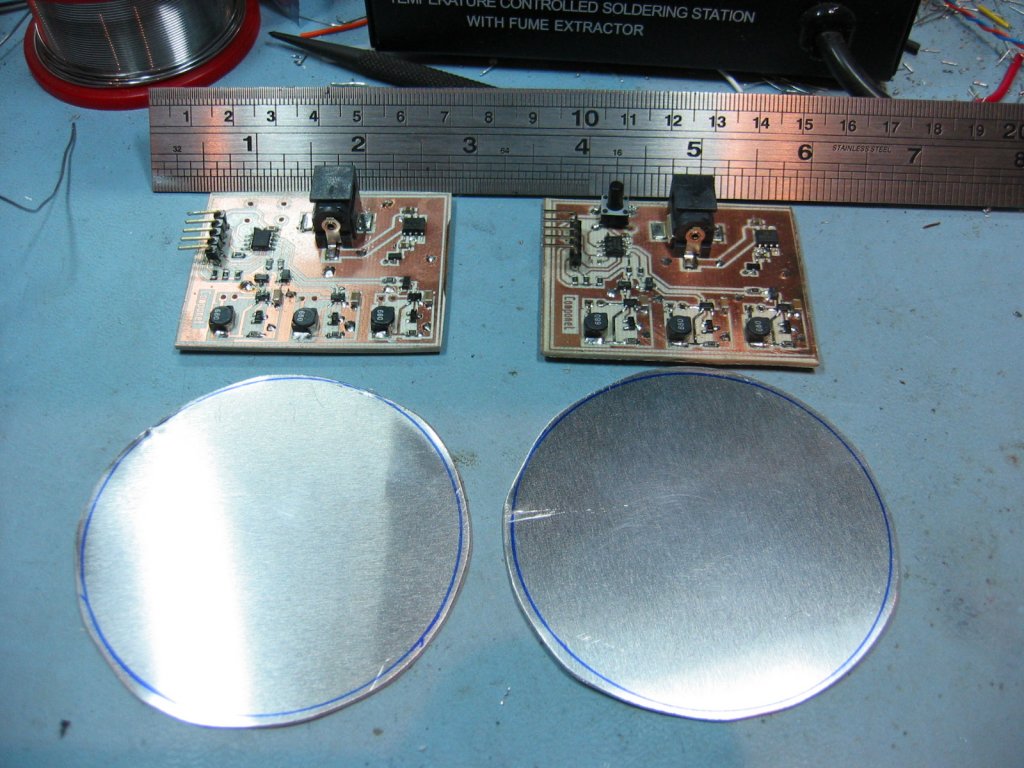
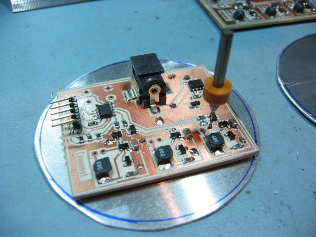
Version 3 PCB
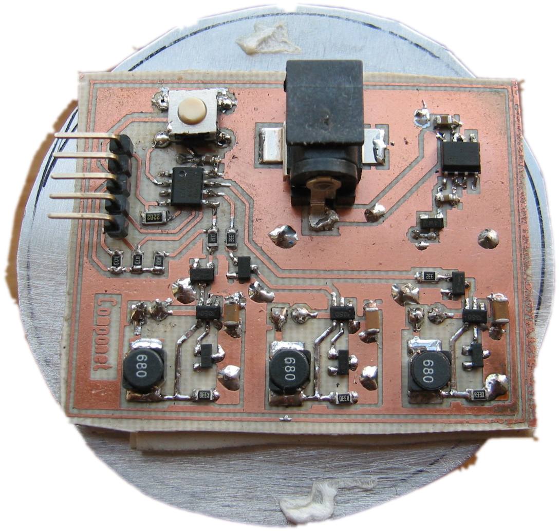
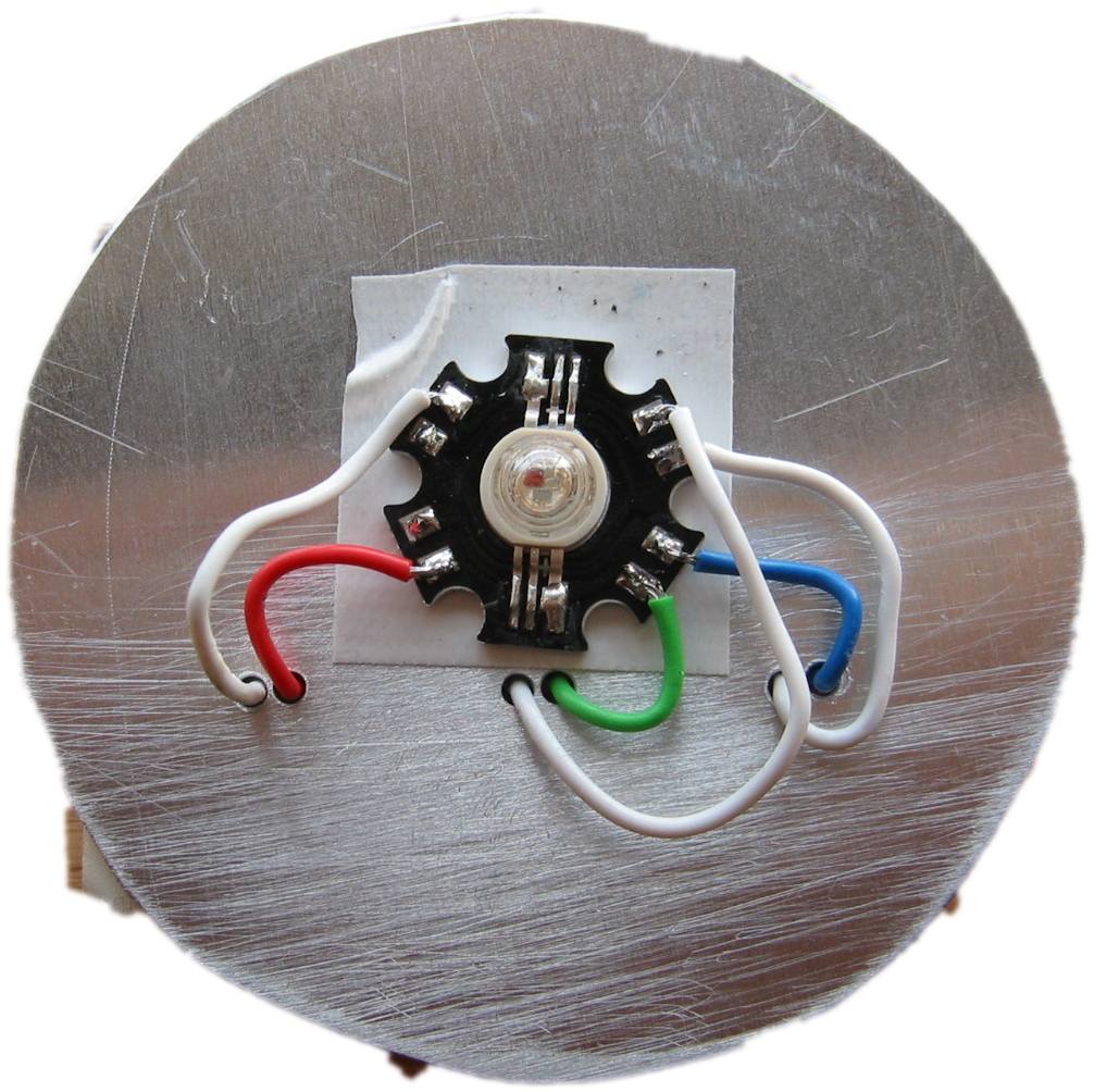
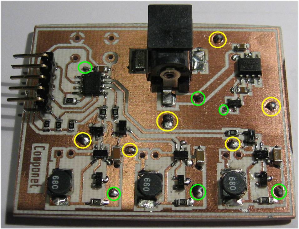
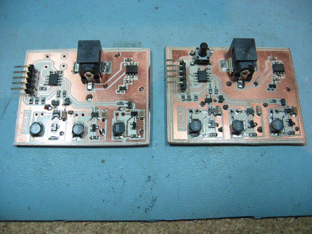
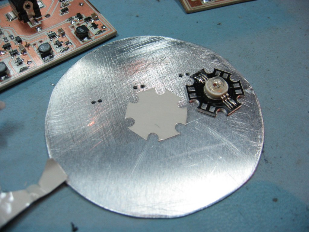
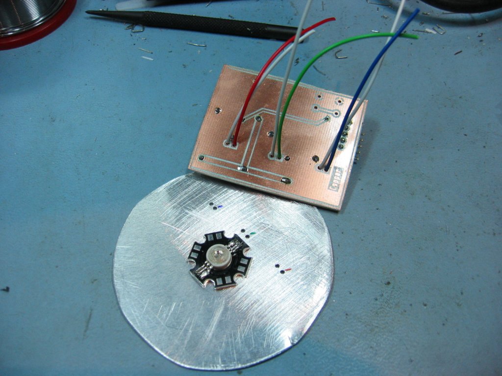
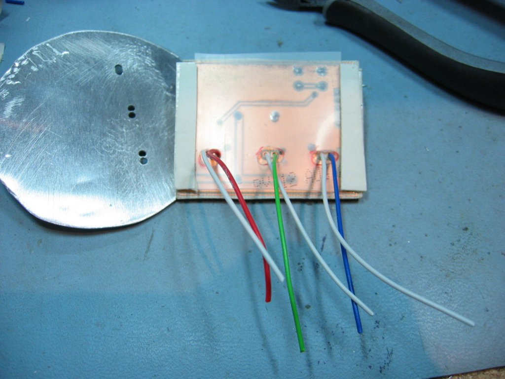
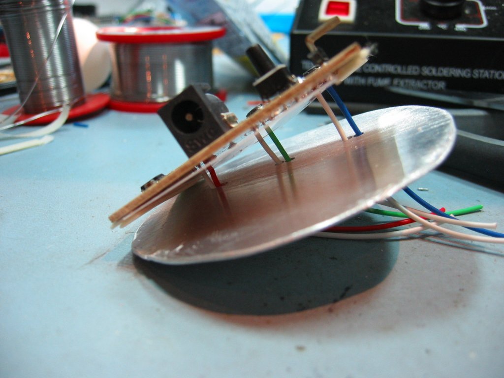
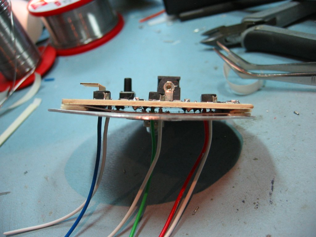
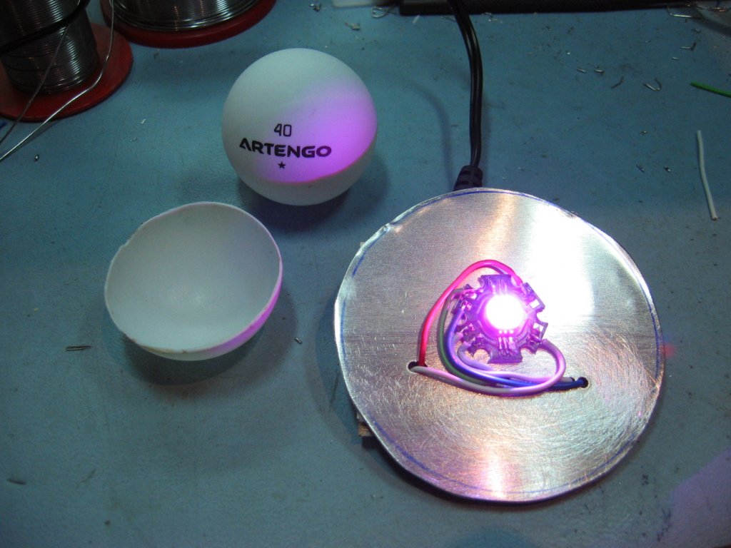
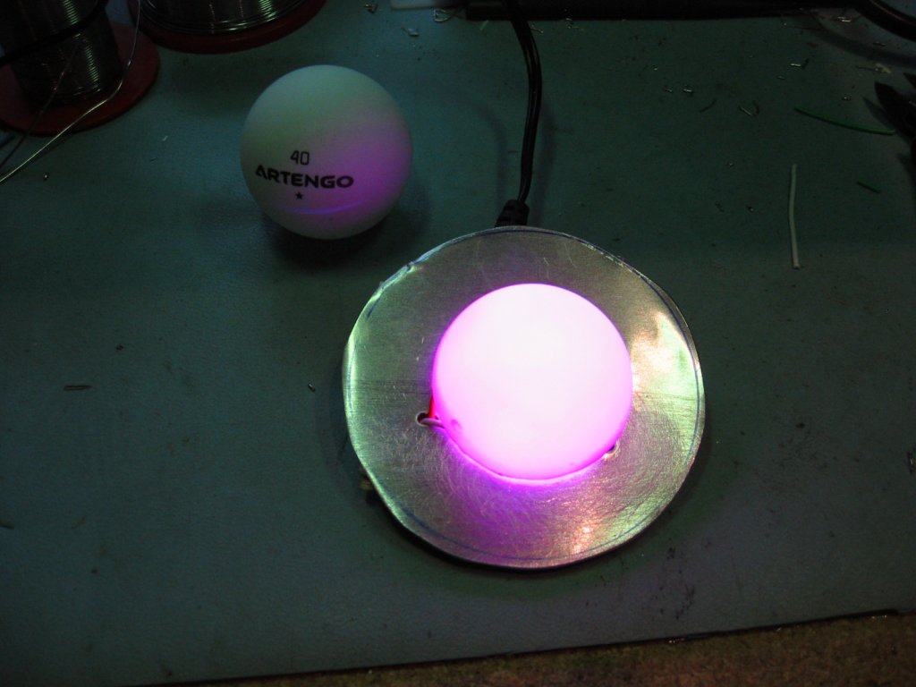
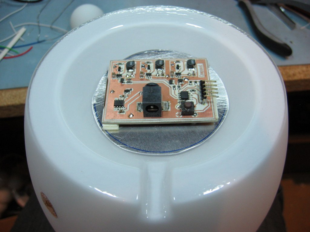
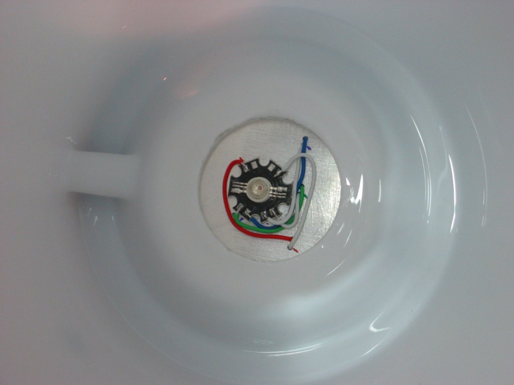
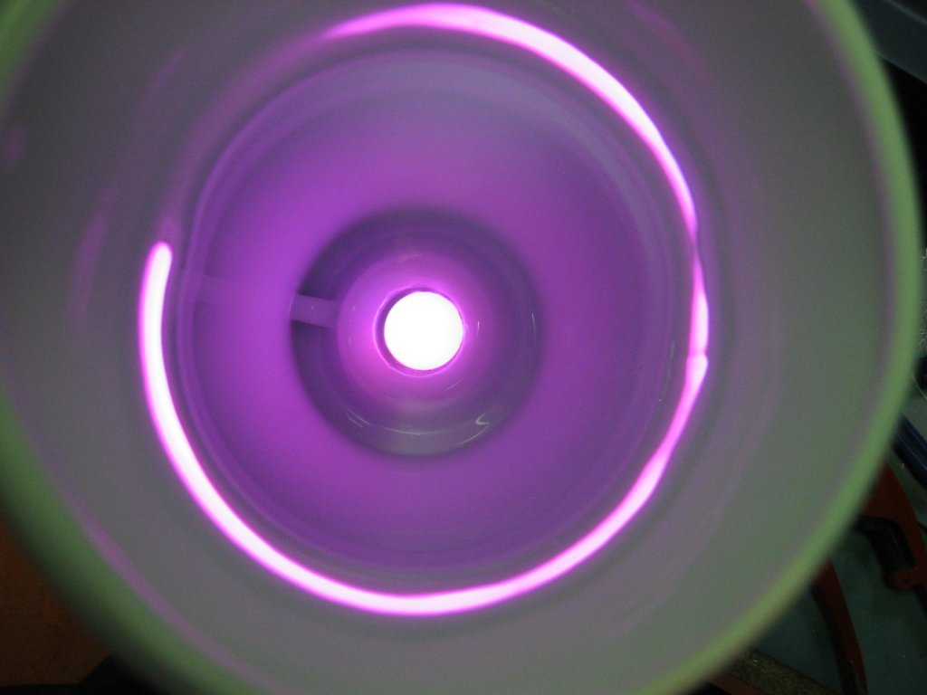
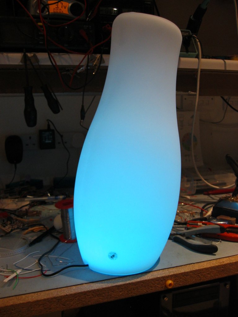
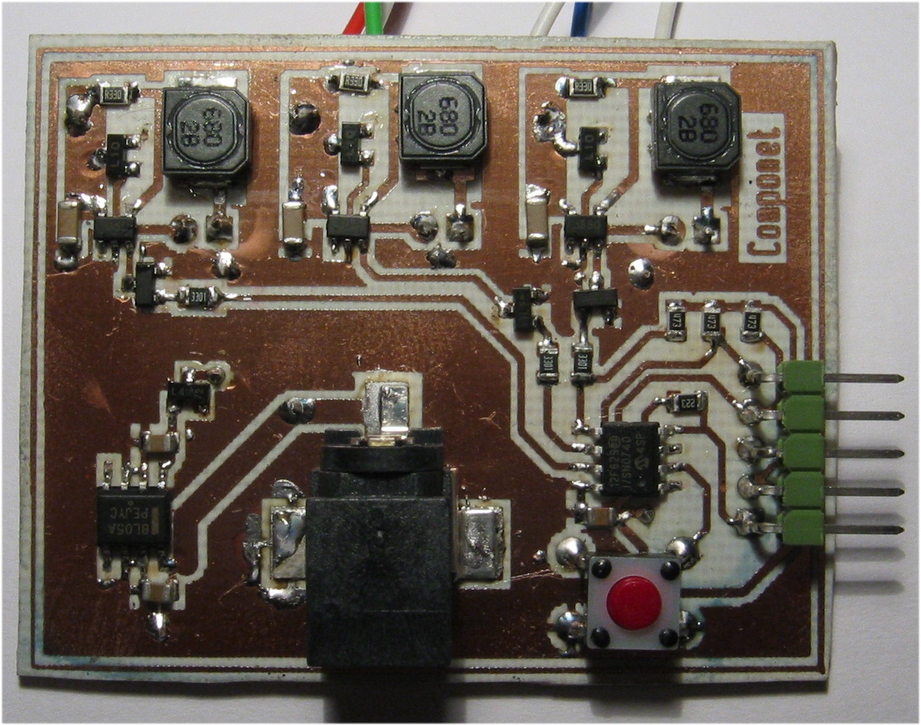
The pad size for the three inductors is SM2512. There are such a variety of inductors that could be used here with so many different footprints. I've left some clear area around the pads to facilitate the use of various inductors but you should make sure that the ones you do use aren't going to touch other areas of copper. This may require some creative positioning of the inductors. The RGB LEDs connect with the anode to the inductor and the cathode to the track that disappears under the ZXLD1350's. This should be apparent from the schematic but I'll mention it anyway. The 5 pin ICSP header needs soldering on the component side of the PCB and the middle pin also needs soldering on the copper side. It can be fitted to either side of the board depending on how you are going to mount the PCB, but you must make sure you solder it so it connects all the PCB tracks. This probably makes more sense if you look at the PCB. The push button switch can be mounted on either side of the PCB to suit your specific application. The surface mount DC power socket is a Switchcraft RASM722 2.1mm SMT Power Socket. (Rapid Electronics P/N 20-0896) 0.33 ohm SMD resistors and ZXLD1350 can be sourced from Farnell The 3 Watt RGB LED can be difficult to source, Rapid Electronics did have one, Farnell only do the Lamina Atlas which isn't suitable for this project. The only other source seems to be buying from sellers in Hong Kong or China through E-Bay. I've done this and even with postage it can be cheaper than UK suppliers, although it can take 10-14 days to arrive. I've used this company http://stores.ebay.co.uk/Sure-Electronics The LED is fixed to the aluminium disc using Adhesive Thermal Pads. In the UK you can get this from Rapid Electronics and Farnell.In the photographs below, the PCB is fixed to the aluminium disc using thick (foam backed) double sided tape. The tape is doubled up to give some clearance between the disc and underside of the PCB and a thin sheet of plastic (from take-away food container) is used to provide insulation between the two. The depth of the recess in the base of the lamp requires that you make the whole assembly as shallow as possible, otherwise the body of the DC power connecter will be below the bottom of the lamp base. Keep this in mind when assembling it. A ping pong ball, cut in two makes a good light diffuser. I've also used opaque tops from aerosol tins to good effect. Although this specific application makes use of a single package RGB LED, it is equally suited to driving separate red, green and blue LEDs. It can also drive 3 pairs of series connected LEDs. However, it cannot be used with RGB LEDs that have a common anode or cathode. Worth checking out are the Lamina Atlas RGB LEDs which
contain 3 pairs of series connected LED dies in one package. These are
very bright, just remember to use a heatsink capable of dealing with
6.6W heat dissipation. It works well with the controller described here
but the aluminium disc shown with this project can't handle the heat so
if you're thinking of using one you'll need to do some redesign work. Warning: Do not look directly into high brightness LEDs; it can damage your eyes.
|