This is a new
'generic' version
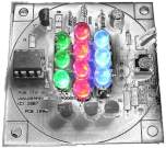
of the code for the 12F6xx based standalone RGB LED controller
projects on the website. It can be used with the following
projects.
This code adds a hold
function that allows the colour currently being displayed on the
LEDs to be 'frozen' at any point. The colour and hold state
are saved and restored across a power cycle so if you find a colour
you really like you can now hold the display and enjoy it.
This is a feature
release code version, not a bug-fix for the original code. You may
prefer the functionality of the original code release, for that
reason both versions are available for download.
When the PIC is first powered on after
programming, it should start running the first RGB sequence found. If
you're using the original sequences supplied with the code here it will
run a sequence of red-fade out, green-fade out, blue-fade out
repeatedly.
User control of the RGB Driver is
done using the SW1 switch which performs multiple functions as
described in the following section.
Single press to Hold / Run current
sequence You can press SW1 at any time to stop the sequence running and hold
the colour being displayed at that moment in time. Pressing
SW1 again will start the sequence running.
If the controller is powered off while in the hold state when it is
next powered on it will remain in the hold state displaying the same
colour.
Double press to Select Next
Sequence (press SW1 twice less than 0.5 second apart; think
'double-click' computer mouse button)
Step through all available sequences. When the last sequence has been
reached it will go back to the first available sequence. Each time
the SW1 switch is 'double clicked' the RGB LED PWM values are set back to 0 (LEDs
off) and the new sequence will start running.
When stepping through the sequences it always starts each new
sequence in the Run state, even if it was previously in a Hold state
Press and hold to enter / exit sleep state Press and hold SW1 switch for about 1.2
seconds to put the PIC into sleep mode. Once in sleep mode, press
the SW1 switch for about 2 seconds then release it to wake the PIC from
sleep. If the SW1 button isn't held for two seconds the PIC returns to
sleep
About 10 seconds after the SW1
switch is last pressed the currently selected sequence number, RGB
colour values and Hold state are saved to
non-volatile EEPROM memory. When the RGB LED driver is next
powered on, the saved sequence number is read back and will
automatically start running the sequence. If it was in a Hold
state at power off it will power on and remain in the 'Hold' state
until SW1 is pressed again.
Anytime the PIC is put into sleep mode
by holding SW1 switch down, the currently selected sequence, displayed
colour and Hold state will be
saved to EEPROM.
The source code comprises a single .ASM file and four .INC files.
All five files are required and should be extracted to a single
directory on your computer. To reassemble the code, open the
genrgbsa_main.asm file, then select Project - Quick Build from the
MPLAB IDE menu bar.
Quick guide to
re-assembling the code with MPLAB IDE can be
found here.
This is a generic code version that will work with several projects
on the website. The code in the ZIP file is ready to use with
the 'RGB LED PWM Controller' project based on PCB100B.
Notes
for use with 350mA RGB LED PWM Driver You can
also use this code with the 350mA RGB LED PWM driver (V2/V3
hardware) described elsewhere on this website. To do this you
will need to make a small change to the genrgbsa_main.asm file as
described below.
Open the genrgbsa_main.asm file in MPLAB.
At the top of the file you will see
the text shown below.
You must change the '2' to '0' before
you do the 'Quickbuild' to assemble the code.
It will then work
correctly with the 350mA hardware.
;
-------------------------------------------------------------------------------
; *** IMPORTANT ***
; For 5mm RGB LED driver built on PCB100B set cDriveLevel equ 2
; For 350mA RGB LED driver V2/V3 set cDriveLevel equ 0
;
cDriveLevel
equ
2
; 0 = output low turns LED on
; 1 = output high turns LED on
; 2 = output determined by GPIO4
; GPIO4 hi -> active high
; GPIO4 lo -> active low
When set
to a hold state, the current RGB values are saved to EEPROM.
If you want to know the RGB values of your favourite colour, read
the EEPROM data back out using your programmer. The Red, Green and
Blue data is saved at EEPROM address 0x02, 0x03 and 0x04
respectively. (note. this data is only valid while in the hold
state)
The
Sequence data
format is identical to that used with the original code.
You can assemble the version 3 code using the same SequenceData.inc
files you have used with the original version of code.
The only
caveat is that the Version 3 code is bigger so it uses more of the
PICs program memory which leaves a bit less for the sequence data.
If you see
a 'Warning[220]' messagein MPLABsimilar to
the example below then you're sequence data file is too big to fit
in the PICs memory.
Warning[220] C:\CODE\GENRGBSA-MAIN.ASM 158 : Address exceeds maximum
range for this processor.
Try
removing a sequence or two from your file and then reassemble.