| |
|
Dual
Output PSU
with adjustable voltage
for Scalextric and other slot cars
|
|
Overview
I designed this PSU to use with the
Scalextric Sport slot car racing set my nephews got for Christmas.
Being technically minded when the kids got the set I couldn't help but
have a look at the AC power adapter and how it delivered DC power to the
track. When I stuck my multimeter across the track I discovered that
when two cars were going flat out down the track and one of them crashed,
the voltage delivered to the remaining car increased by as much as 2
volts. The fact that even the
supplied power base is designed to allow connection of separate PSUs to
each track hints that, as is so often the case, it was specified on price
not performance.
I also noticed that my youngest nephew
had trouble controlling the speed of the cars and I figured that if we
could reduce the overall voltage delivered to the track he'd be able to
control the car more easily and keep it on the track longer.
The final piece to this project was the
Race Start Controller (RSC) that I had also been working on. It occurred
to me that with a custom PSU, it should be possible for the RSC to
shut-off power to the track when a car jumps the start.
Finally, if you just want to build the
PSU and don't want to use it with the RSC you can do that too. It will
work just fine on its own.
|
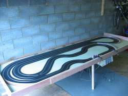
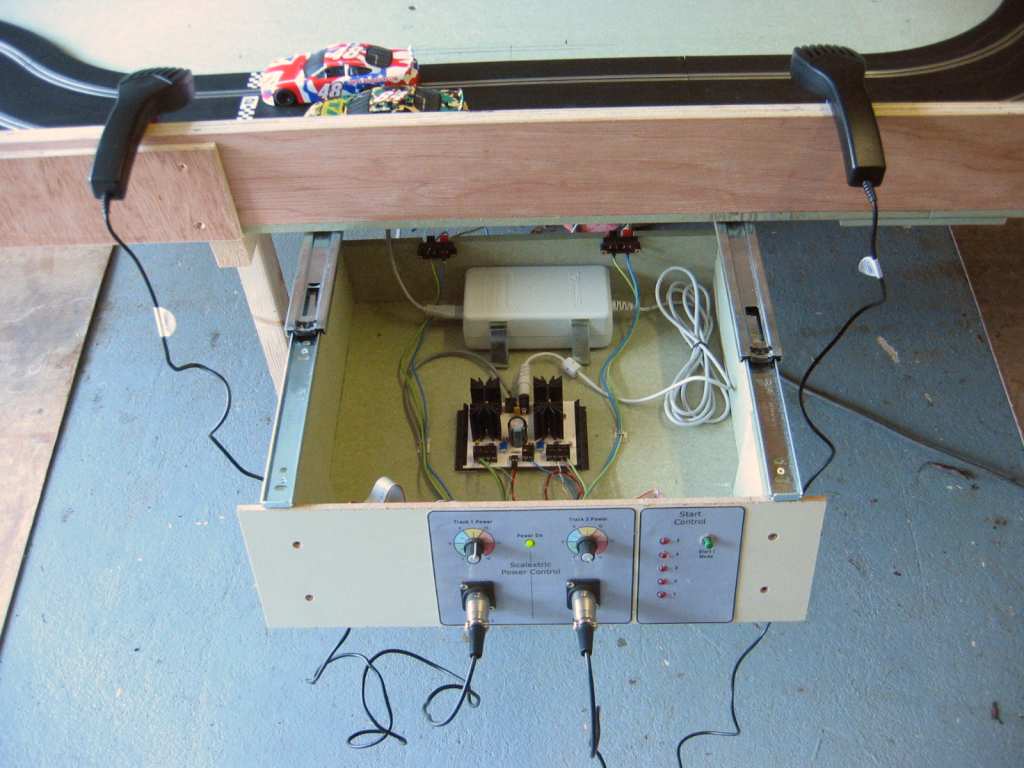
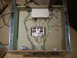
12ft
x 4 ft layout |

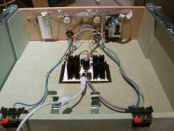
Control draw on sliding rails |

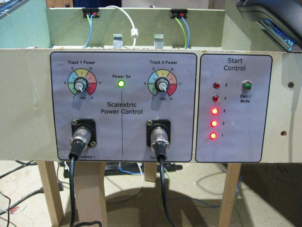
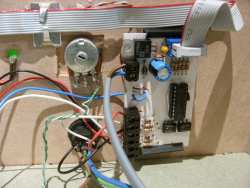
Front panel - I've ditched the 3.5mm jacks
for the throttles and replaced them with 3-pin XLR connectors |
Schematics
|
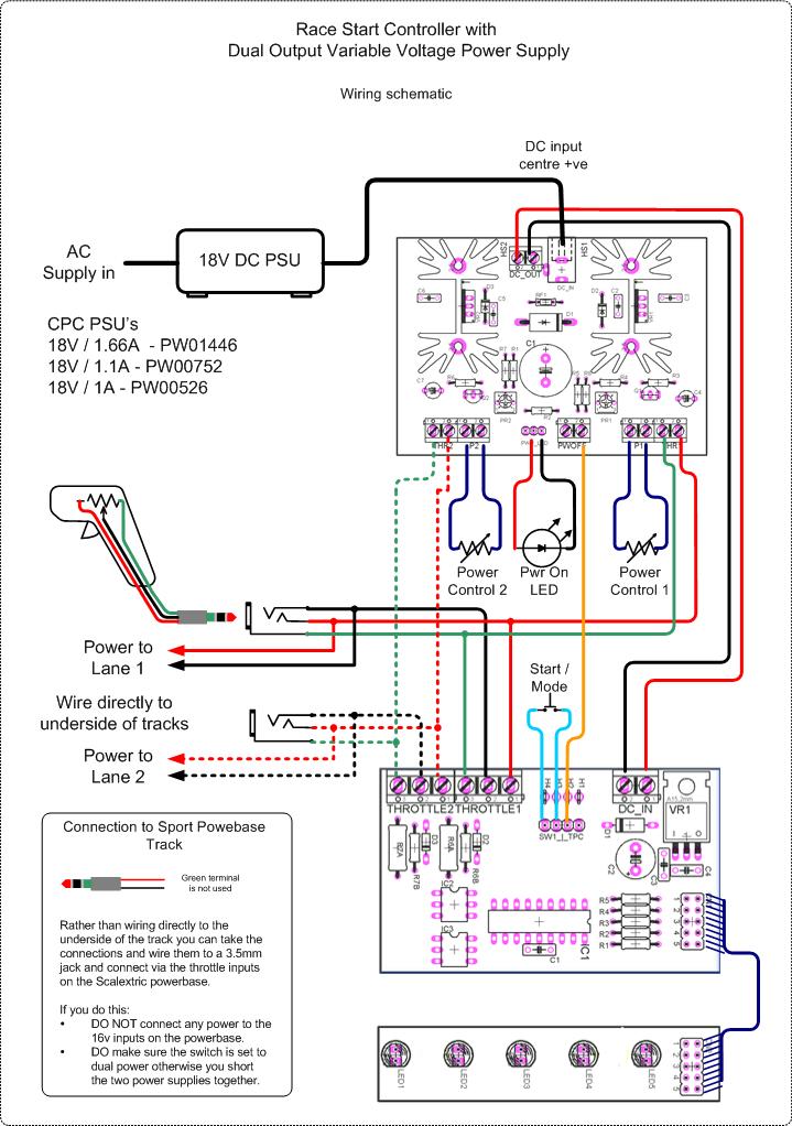
| The
wiring and circuit schematics show how to connect the PSU to the track and
to the Race Start
Controller
The PSU comprises two identical voltage
regulator sections. The schematic only shows one, the second one is
identical and on the PCB component overlay parts names appended with the
letter 'a' refer to the second voltage regulator section.
|
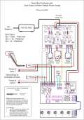
Wiring Schematic
click here for PDF version
|
Race Start Controller Schematic
click here for PDF version
|
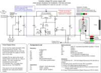
| Circuit
Description
The Dual PSU is built around two LM317T
adjustable voltage regulators. These devices are capable of supplying
a regulated output voltage from 1.25 to 37 volts at up to 1.5amps.
They feature current limit protection and thermal overload protection
so are fairly bullet proof making them ideal for this application.
At the input to the circuit is RF1. This
device is a self-resetting fuse and it is included as a safety
feature. If this fuse trips, the power LED1 will go out. You
will then need to remove the cause of the overload and also remove any
other loads from the PSU before it will reset. In other words don't have a
throttle wide open waiting for the power to come back - it won't.
Diode D1 protects the circuit from
accidental reverse polarity connections to the DC input. Since this circuit
is designed for use with any suitable 18V PSU it is not inconceivable that
some may have a DC plug wired for centre negative. It also protects
any attached PSU from C1 discharging into the input. I've found that
the output from some SMPSU's will dip by a couple of volts when the load
goes from zero to 400mA, a scenario typical of two cars accelerating from a
standstill. Capacitor C1 helps reduce this dip at the input to the
regulators, you may find that you can omit this without any adverse effects.
The components around VR1 follow the basic
LM317 reference designs. Diode D2 prevents damage to the voltage
regulator in the event that the voltage at the output exceeds the input
voltage. Capacitor C2 provides decoupling at the input to the regulator.
The components around the adjust pin of the
regulator set the output voltage. Resistor R4 sets the minimum
output voltage to ~7volts. The preset PR1 in parallel with P1 is used
to set the maximum output voltage. Once PR1 is set, P1 allows the
operator to vary the output voltage between the minimum and preset
maximum.
Transistor Q1 is used to shut-off the
output. Q1 is turned on when the 5 volt signal is applied to the base via
R5 from the 'Power Control In' input. This pulls the adjust input of
VR1 to ground, bypassing the resistor network and causing the output of
VR1 to drop to 1.3volts. In practice this is insufficient for a slot car
motor to actually move the car, particularly from a standstill.
Resistor R5 and R2 pull the base of Q1 low, ensuring that Q1 is turned off
when there is no control input.
Increasing the output current
The LM317K regulator can deliver up to
1.5amps. If you replace RF1, the 1.1amp resettable fuse with a 3 amp rated
part (Rapid Electronics Part No 26-0805 ) and find a 3 amp or greater
rated PSU you can deliver up to 1.5amps to each lane. Diode D1 is only
rated at 3amps so the design is not really suitable for delivering more than
3amps total.
|
|
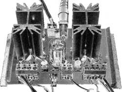
The PCB was designed
using CadSoft Eagle. You can download a free version from their
website http://www.cadsoft.de/
Eagle PCB Artwork file
PCB
artwork in PDF format
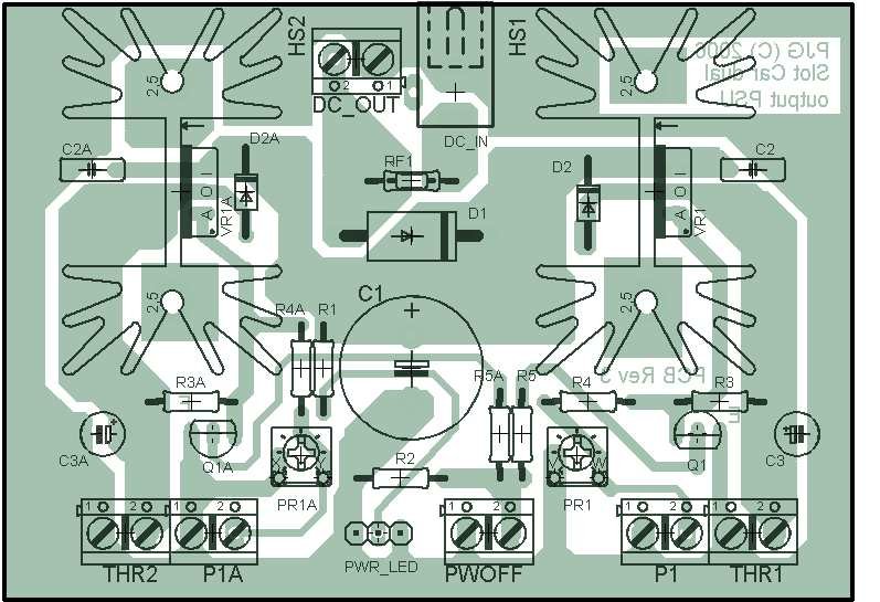
On the component
overlay, component names with an 'a' appended are the duplicated parts
of the schematic for the second PSU.
If you use the artwork
from the PDF to make the PCB, check that the output is to scale.
Overall board dimensions are 2.7" x 3.85".
|
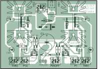
PCB Component Overlay
|
DC
Input Power Supply I
deliberately chose not to build a transformer based power supply for the
input to this circuit for the following reasons
-
It
avoids having AC mains voltages present and all the safety issues that
involves.
-
For
the cost of the transformer and associated components you can buy a
suitable Switch Mode PSU.
-
Switch
Mode PSUs are more efficient and generally have over voltage,
short-circuit and thermal protection designed in.
For
these reasons I chose to use a switch mode PSU to use as the input to this
circuit. One reason not mentioned above is that in my work I have
access to assorted redundant SMPSUs. The one I've used on the final
version of this is an 18volt 1.1amp PSU from an HP Scanner. I've tried
a 22volt 2amp PSU I bought on E-bay for £6 which also worked
fine.
You
need a PSU that can supply at least 1 amp, a bit more won't hurt but it
won't make your cars go any faster either. You need to supply the
circuit with at least 4 volts more than the maximum output at the
track. In theory you could get away with a 16volt input but I
recommend 18volts. You also need to make sure that it will work
without any load, most of the power-brick type SMPSUs will, but make sure
the one you buy does.
A
good place to look is CPC at www.cpc.co.uk.
I found the following, all of which appear to be suitable (though I
haven't tried them)
18V / 1.66A - part #
PW01446
18V / 1.1A - part # PW00752
18V / 1A - part # PW00526
Circuit construction
and setup
When constructing the circuit on the
PCB, don't be tempted to install the big components first, they make
it difficult to install the small parts afterwards.
-
Install
RF1, resistors, preset, diodes and capacitors except C1 and solder
to the PCB
-
Next
install the DC power connector and PCB screw terminal blocks
-
Now fit
both heat sinks and solder the lugs to the PCB.
-
With the heat sinks
fitted install the voltage regulator IC's. You might want to
apply a bit of heat sink compound to the back of the
regulator. Push the legs through the PCB holes but don't
solder them in place at this stage. Using an M3 screw and
nut attach the regulator to the heat sink. Tighten the
screw being careful not to twist the regulator. A tip here is to
ensure that the screw is fitted so that it is facing the edge of
the PCB otherwise you can't get a screw driver on it
When
the voltage regulator is bolted to the heat sink, the heat sink is
electrically connected to the regulator output. It is important
that the heat sinks do not touch any other components or metal
work inside an enclosure.
-
Once the
regulators are attached to the heat sink, solder them to the PCB
and then fit capacitor C1
-
With all
the components fitted, have a good look at the track side of the
PCB to ensure there are no solder bridges and all the joints are
sound.
Once you're
happy with the assembly of the board connect a suitable DC power
supply to the DC input.
-
Measure
the voltage at the DC_out connector on the PCB. This should be the
same as the rated output of the DC power supply.
-
Now
measure the voltage at the THR1 and THR2 connectors. The
voltage should be somewhere between 7 and 16 volts. If you adjust
preset PR1 / PR1A you should see the output voltage change.
-
Next
attach the potentiometers P1 / P1A to the terminal
connectors on the PCB.
-
Adjust
preset PR1 to its mid position.
-
While
measuring the output voltage at the THR1 terminal adjust P1 fully
clockwise then fully counter clockwise. Measure the voltage
at the THR1 connector in both positions, then leave P1 set at the
position where the measured voltage was highest.
-
Now adjust
preset PR1 until the voltage measured at the THR1 connector is 12.5
volts.
(You can adjust the maximum output up to about 14 volts which will
make the cars go faster - however you do so at your own risk - if
you burn the cars motor out or damage it in any other way it was
your choice)
-
Repeat the
last three steps with THR2/P1A/PR1A to setup the maximum output on
the second PSU.
The circuit is now complete and ready
to connect up as shown in the wiring schematic above
Notes for use with the Race
Start Controller
|
|
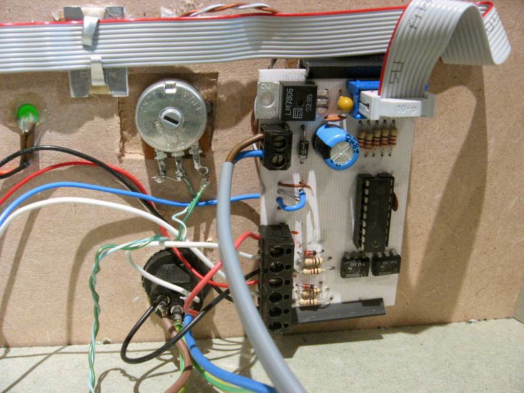
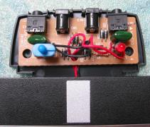
Don't follow my wiring colours here,
I hooked this up before I did the schematics
|
|
|
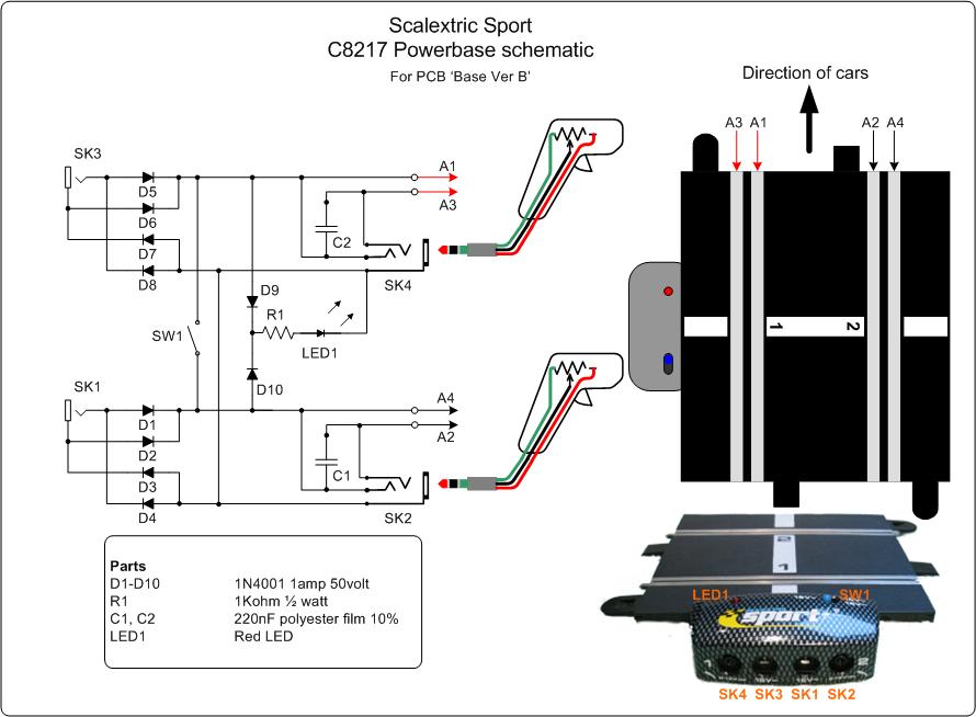
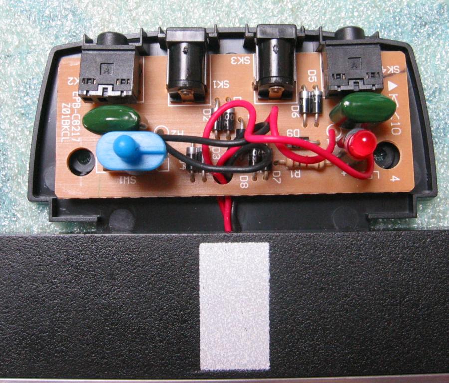
| A schematic
diagram of the internals of the Sport Powerbase track part
C8217.
If you want to connect the
PSU to the track via the Powerbase, rather than wiring
directly to the underside of the track you can. Details
of how to do this are shown on the Wiring Schematic above.
If you do this you must
ensure that the Switch is set for dual PSU and you don't
connect anything to the 16V inputs on the Powerbase.
|

|
 |
| |
PDF version |
|
|
Parts
Listing
-
All
Rapid parts/descriptions correct at 19-Sept-2008. You should
check part# and descriptions are correct when ordering in case
I've made a mistake transferring them onto this page.
-
The
resistors are sold by Rapid in packs of 100. You may find it
cheaper to buy some or all of the parts from other sources - I make no
recommendation.
-
You will also needs some short
lengths of wire for the interconnections between the PCB, potentiometers. Rapid sell a pack of 11 colours x 2M lengths of stranded
equipment wire, Part # 01-0108

|
| Qty |
Part Number |
Description |
| 1 |
55-0120 |
5mm green LED |
| 2 |
47-3318 |
LM317T voltage regulator |
| 2 |
47-3130 |
1N4001 diode |
| 1 |
47-3144 |
1N5401 diode |
| 2 |
81-0066 |
BC548B |
| 1 |
26-0780 or 26-0740 |
1.1A polyswitch fuse |
| 2 |
67-0608 |
2K, 6mm cermet preset
potentiometer |
| 2 |
65-0710 |
4.7K, 16mm potentiometer |
| 2 (sold in packs of 100,
order Qty 1) |
62-0382 |
3.3K ohm 0.25 watt resistor |
| 1 (sold in packs of 100,
order Qty 1) |
62-0374 |
1.5K ohm 0.25 watt resistor |
| 1 (sold in packs of 100,
order Qty 1) |
62-0410 |
47K ohm 0.25 watt resistor |
| 2 (sold in packs of 100,
order Qty 1) |
62-0354 |
220 ohm 0.25 watt resistor |
| 2 (sold in packs of 100,
order Qty 1) |
62-0370 |
1K ohm 0.25 watt resistor |
| 2 |
11-1046 |
10uF / 25volt Tantalum
Capacitor |
| 1 |
11-0765 |
2200uF / 35volt Radial
Electrolytic |
| 2 |
08-0235 |
100nF disc ceramic
capacitor |
| 6 |
21-0440 |
2-way, 16A interlocking
terminal |
| 2 |
36-0316 |
TO-220 heatsink, 3.9oC/Watt |
| 1 (to suit DC
power supply) |
20-0962 |
2.5mm PCB mount DC power
socket |
| 20-0960 |
2.1mm PCB mount DC power
socket |
|