goto Home


Idiosyncrasies of the instruction set

Before you start programming the PIC in assembler, have a thorough read of the datasheet and pay attention to what the instructions do. The instruction mnemonics can be misleading and some instructions don't set flags you'd expect them to.  Anyway, here's my 'top ten tips' for the PIC 14-bit instruction set as found on the 12F and 16F PICs

  1. SUBLW does not subtract the literal from W, it subtracts W from the literal, and that matters.

  2. DECF and INCF instructions set/clear the 'Z'ero flag according to the result of the operation BUT.....

  3. DECFSZ and INCFSZ instructions don't affect the 'Z'ero flag but they do 'skip next' if the result was 0.

  4. MOVLW does not set/clear the 'Z'ero flag.

  5. RETLW does not set/clear the 'Z'ero flag.

  6. To test if W contains 0 just use IORLW 0x00 or ANDLW 0xFF; either will set/clear the zero flag.

  7. ADDLW  0x00  will set the 'Z' flag if W contains 0 and clear it if it doesn't BUT it will also leave both the 'C'arry and 'DC' digit carry flags clear while leaving the W register unchanged.

  8. MOVF  register,F  appears to do nothing, but it will set/clear the 'Z'ero flag.

  9. RLF and RRF instruction affect the 'C'arry flag, but not the 'Z'ero flag, even if the result of the shift leaves the register contents == 0.  (This is true even if the destination of the Rotate is the W register)

  10. SUBLW 0x00 will change the value in W to the 2's compliment of the original value in W - useful (but don't forget it will affect the 'Z'ero, 'C'arry and 'DC' digit carry flags too)


MPASM Pseudo Mnemonics

The Microchip MPASM (MPLAB IDE) assembler supports a number of Pseudo Mnemonics.  These are just text substitutions for regular PIC instructions but they can make code written using them much more readable and easy to follow.

For example the regular instruction BCF STATUS,C will clear the carry flag in the status register.  The pseudo mnemonic CLRC does the same thing but it's much easier to 'see' what is being done.

A full list of these  can be found here: Pseudo Mnemonics List

See also the Microchip MPASM Quick Reference Card


Subtract instruction

Since subtraction isn't commutative it matters what is being subtracted from what.

First thing to remember is that the value in the W Register is always subtracted from the operand in the subtract instruction whether that's a literal value or a file register. 

The 12/14 bit PIC instruction set has two subtract instructions,

subwf :  W is subtracted from the value in the file register.   'File Register' - 'W Register' = Result
sublw :  W is subtracted from the literal word.   'Literal word' - 'W Register' = Result

Remember: Operand - W

The carry and zero bits in the STATUS register are set by the subtract operation as follows:

  Carry Flag Bit Zero Flag Bit
Operand > Wreg 1 0
Operand == Wreg 1 1
Operand < Wreg 0 0

There is no subtract-with-carry instruction in the PIC 12/14 bit instructions set.  The current state of the carry flag is ignored by the subtract instruction, so you don't have to clear/set it before a subtract instruction executes.  However that also means if you are going to do a multi-word subtract operation your code will have to manually test and handle the carry.

Below is some code that shows how the subtract instruction works:

        movlw 5
      movwf
var1   ; Set Var1 == 5

    
; subwf var
     ; var - Wreg -> destination (var or Wreg)
     ;----------------------------------------

      movlw
4
      subwf
var1,W ; Var1 - W = Result  [5 - 4]
                  
; Result = 0x01, C=1, Z=0

      movlw
5
      subwf
var1,W ; Var1 - W = Result  [5 - 5]
                  
; Result = 0x00, C=1, Z=1


      movlw
6
      subwf
var1,W ; Var1 - W = Result  [5 - 6]
                  
; Result = 0xFF, C=0, Z=0

    
; sublw k   
     ; k - Wreg -> Wreg
     ;---------------------------------------

     movlw 4
     sublw
    ; 5 - 4 = 1
                
; W=0x01, C=1, Z=0

     movlw
5
     sublw
    ; 5 - 5 = 0
            
     ; W=0x00, C=1, Z=1

     movlw 6
     sublw
5      ; 5 - 6 = -1
                 
; W=0xFF, C=0, Z=0 


Compare and branch

The PIC instruction set doesn't have much in the way of compare and branch instructions.  The following code will compare a File register with the contents of W and then do a test and branch.  

_CMP      movlw  CompTo      ; put the value to compare with in W
          subwf  SomeVar,W   ; subtract W from the File Register
                             ;
  you want to compare with and put
                                                          ; result in W (this preserve file register)

_BEQ      btfsc  STATUS,Z    ; Test for Zero flag set
          goto   _Equal      ; SomeVar = CompTo

_BLT      btfss  STATUS,C    ; Test for Carry Flag Clear
          goto   _Less       ; SomeVar < CompTo

_BGE      btfsc  STATUS,C    ; Test for Carry Flag Set
          goto   _GtOrEq     ; SomeVar >= CompTo
                             ; On its own this will test

                             ; for a '>=' condition but if it
                             ; follows a test for '='then
                             ; it will succeed only for a '>'
                             ; condition

The Microchip MPASM assembler supports a whole set of pseudo mnemonic branch instructions, see them here 

If you just want to test a file register to see if it is zero you can do this:

          movf   SomeVar,F

_BEQ   
   btfsc  STATUS,Z    ; Test for Zero flag set
          goto   _Equal      ; SomeVar = 0

The Microchip MPASM assembler supports a pseudo mnemonic, TSTF somervar, which is the same movf SomeVar,F by another name. 

or to test for not equal to zero use this:

          movf   SomeVar,F

_BNE   
   btfss  STATUS,Z    ; Test for Zero flag clear
          goto   _NotEqual   ; SomeVar /= 0

If you want to test the W register to see if it is zero try this:

          iorlw   0x00       ; Sets Z flag if result is zero
                             ; leaves W unchanged.

                             ; Test with _BEQ or _BNE code from
                             ; File Register test example above.


How to Decrement the W Register

The PIC doesn't have a decrement W instruction but you can achieve the same thing with this single instruction. This is straight from the Microchip data sheets.  The workings of this may not be immediately apparent. The Add and Subtract instructions on the PIC use 2's Complement representation.  What this instruction is actually doing is adding the W register to -1 which results in W containing one less than it started with.

_DEC      addlw  0xFF       ; Add W to -1 


You'd think you could do a Decrement of W by using the subtract instruction like the example shows below but you can't. Here's why.... this instruction is actually subtracting the contents of W from 1 and not 1 from W.
Since 5 + -1 is the same as -1 + 5, both of which equal 4 the add works but 1 - 5 equals -4, not what we wanted.

_DEC      sublw  0x01       ; Subtract W from 1

Don't forget that the 'addlw' instruction will always affect the zero, carry and digit carry flags, where the 'decf' instruction only affects the zero flag.


How to Increment or Decrement a register without affecting any flags

The incf and decf instructions set/clear the 'Z'ero flag in the status register. However, the incfsz and decfsz instructions don't affect any flags.

So while this will affect the 'Z'ero flag

incf    register,F

this will not

incfsz  register,F
nop

Okay, so you have to waste one program memory word with the 'nop' instruction, but if you happen to need to increment or decrement a register without changing the Z flag in the status register it can be a quite useful.


Test W register for 0 and clear Carry and Digit Carry in one instruction

This may seem an obscure thing to want to do but I have used this in a practical application which is how I came across it.  

When you use a RETLW instruction to load W, the Status register zero flag isn't affected. In my application I was using a lookup table with return data of 0x00 as an end of data delimiter so I needed to test W for a zero value and also needed to clear the carry bit for a shift instruction that followed.

Method 1.

iorlw    0x00           
btfsc   
STATUS,Z

goto
     _someLabel
bcf     
STATUS,C
;
At this point Status flags are Z=0 C=0 DC=?

Method 2.

addlw    0x00
btfsc   
STATUS,Z

goto
     _someLabel
;
At this point Status flags are Z=0 C=0 DC=0


Exchange Two File Registers

This code block exchanges the contents of two file registers using the W register.  The smart thing about this code is that it doesn't require the use of a temporary file register to store an intermediate value

_EXCH     movf   filereg2,W
          xorwf
  filereg1,F
          xorwf  filereg1,W
          xorwf  filereg1,F
          movwf  filereg2

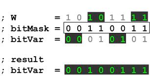
I take no credit for this but it's pretty neat in its workings and can be very useful.


Copy specific bits from W register into GPR variable

This code copies the bits in the W register specified by the bitMask into the bitVar variable while leaving the remaining bits in the bitVar variable unchanged.

; define bit mask constant to suit application
bitMask 
 equ  b'00110011'

               ; enter code block with
               ; bits to copy in Wreg

              
xorwf   bitVar,W
               andlw   bitMask
               xorwf   bitVar,F


8 bit unsigned window comparison

This function compares the value in the Wreg with a high and low watermark.

It returns with the carry flag set if  minimum <= Wreg <= maximum.  If Wreg is outside these values it returns with the carry flag clear.

; Unsigned 8 bit Window comparaison
; Call with value to compare in Wreg, not preserved on exit
; replace min and max with literal values
; min <= Wreg <= max returns with Carry flag Set
; min < Wreg > max returns with Carry Flag Clear

windowsub  sublw    max
           skpc
           return
           sublw
  (max-min)
           return


Edge Detecting on Inputs

Input edge detection is useful for finding when an input changes state. A practical application is detecting when a switch has been pressed or released.  Implementing a function that can detect either a rising or falling edge is fairly straight forward.

The method used is to first Exclusive-OR (XOR) the previous tested state of the input with the current state and then perform a logical AND with either the current state if you want to find a rising edge, or the previous state for a falling edge.  The current state then becomes the previous state in the next pass.   If you want to find both rising and falling edges, you need to do the XOR but not the following AND.

This code doesn't need to see the actual edge but it will detect when an input has changed state.  It also needs to poll the input fast enough so as not to miss a signal that changes state and back again faster than the polling cycle.  Typically when a user presses a switch it will take several 100mS even if they press it quickly so polling fast enough is quite easy. 

When using it with switches you need to allow for switch bounce, this is were the contacts in the switch make and break several times before settling.  A microprocessor is more than fast enough to see several 'edges' from the switch bounce; therefore the application needs to allow for this.  This can often be done by simply using a hold down timer to ignore further edges seen during the hold down period.

The code below detects low-to-high (rising edge) transitions on PORTB inputs 4-7 and pulses outputs 0-3 high when an edge is seen  (in 4 -> out 0 | in 5 -> out 1 | in 6 -> out 2 | in 7 -> out 3).  
 

                ; define bit mask
C.input_mask    equ             b'11110000'
                ; Detect input bits that change from 0 to 1 - rising edge
                ;
edge.rise       movfw           PORTB                           ; load PORTB to Wreg
                andlw           C.input_mask                    ; mask out I/O bits we're not interested in
                movwf           inputs.this_time                ; save result to variable
                xorwf           inputs.last_time,W              ; XOR last input value with current input value
                andwf           inputs.this_time,W              ; keep only bits that have changed from 0 to 1
                movwf           edge.detected                   ; save result to variable
                movfw           inputs.this_time                ; copy input.this_time to input.last_time
                movwf           inputs.last_time                ; ready for next pass
                call            output                          ; for purpose of the demo, send result to outputs
                goto            edge.rise                       ; run edge detect code loop again
                ; Write edge detect to output
                ; This code is just to show the edge detecion in the simulator.  
                ; In your own code you'll want to do something useful with the edge.detected variable 
output         swapf           edge.detected,W                  ; since we use 4 bits as input and 4 as output on 
               movwf           PORTB                            ; the same port, swap nibbles and write to PORTB
               return
A demo app written in assembler for the PIC16F628A along with the HEX files for the rising and falling edge demos which can be run on the Oshonsoft PIC Simulator are provided below.  The app was written to run on the simulator which doesn't run in real time.  If you try this on a real PIC with LEDs and switches, you won't be able to see anything because the output LED pulses are to fast.


Byte saving 'dirty' return

First, this is a bad programming example, it's perfectly correct as far as the CPU is concerned but it will make the execution of your code difficult to follow, and more difficult to maintain.

With that out of the way, if your code calls a sub-function from within another call, you can save a byte and 2 cycles by using a 'goto' instruction to get to the sub-function and letting the 'return' in the sub-function take you back to the original call.  

Since the stack on the 12/14 bit PICs is only 8 levels deep, in some circumstances this trick can 'gain' you a 9th call, and it will save two instruction cycles.

The examples below demonstrate this.  

 The proper way
                   call  func1
                   ...     

      func1        call  subFunc1
                   return

      subFunc1     ...
                   return


The byte saving way
                   call  func1
                   ...     

      func1        goto  subFunc1
 

      subFunc1     ...
                   return


8 x 8 unsigned multiply


This code multiplies two 8 bit unsigned values with the 16 bit result returned in resHi, resLo.   The code loops eight times during the multiply operation and rather than using a separate variable for the loop count the resLo variable doubles up as both the counter and low byte of the result.

                 ; 8 x 8 unsigned multiply routine.     
                 ; enter with terms to multiply in mult1, mult2     
                 ; resHi, ResLo contain 16 bit result on exit     
                 ; value in mult2 will is destroyed     

_multiply8x8    movfw   mult1           ; load mult1 into W reg
                clrf    resHi           ; initialise resHi, ResLo
                clrf    resLo
                bsf     resLo,7         ; set bit 7 in resLo to use as loop counter
                         
_mloop          rrf     mult2,F         ; rotate mult2 one bit right
                skpnc                   ; test bit shifted out of mult2
                addwf   resHi,F         ; if it was a 1, add W to ResHi
                rrf     resHi,F         ; shift 16 bit result right one bit
                rrf     resLo,F         ; 
                skpc                    ; skip next if carry set as we have shifted 8 times
                goto    _mloop          ; if carry was not set, loop again

                return   

Binary to packed BCD conversion

(If you use this code, please reference http://picprojects.org in your source code, thanks)

This code converts a binary number to a packed BCD number using the shift and add +3 algorithm. If you want to know how it works there are plenty of sites that offer explanations. See here.

There are two versions of the code; an 8 bit conversion and a 16 bit. If you only need to convert a single byte (8 bit number) the 8 bit version is much faster.

The binary number to convert is loaded in to binH and binL prior to calling the subroutine.  The result is placed in  bcdH, bcdM, bcdL.  The routine requires two other working file register variables.  The 8-bit conversion requires the binary value to convert in bin and the results is returned in bcdH, bcdL.  In both versions the contents of binH and  binL or bin are destroyed.

Example. 0xE576  = 58742 decimal

binH binL converts to -> bcdH bcdM bcdL
E5 76 05 87 42

            binL      ;binary number for conversion - low byte
            binH      ;binary number for conversion - high byte
            bcdL      ;packed bcd result low digits
            bcdM      ;packed bcd result middle digits
            bcdH      ;packed bcd result high digit
            counter   ;working variable
            temp      ;working variable

16-bit binary to BCD conversion

Download this code

; file register variables 
; binH, binL, bcdH, bcdM, bcdL, counter, temp
;
need to be defined elsewhere.
;
; binH, binL contain the binary value to
; convert. Conversion process destroys contents
; Result is in bcdH, bcdM, bcdL on return.
; Call _bin2bcd to perform conversion.
;
; Executes in 454 instructions

_bin2bcd    movlw     d'16'
                        movwf     counter
                        clrf     
bcdL
                        clrf     
bcdM
                       
clrf      bcdH

 _repeat    rlf       binL,F
            rlf      
binH,F
            rlf      
bcdL,F
            rlf      
bcdM,F
            rlf      
bcdH,F

            decfsz    counter,F
            goto     
_adjust
            return

_adjust     movlw     d'14'
            subwf    
counter,W
            skpnc 
            goto     
_repeat
            movfw    
bcdL
            addlw    
0x33
            movwf    
temp
            movfw    
bcdL
            btfsc    
temp,3
            addlw    
0x03
            btfsc    
temp,7
            addlw    
0x30
            movwf    
bcdL
            movfw    
bcdM
            addlw    
0x33
            movwf    
temp
            movfw    
bcdM
            btfsc    
temp,3
            addlw    
0x03
            btfsc    
temp,7
            addlw    
0x30
            movwf    
bcdM
           
goto      _repeat
; we only need to do the test and add +3 for
; the low and middle bcd variables since the
; largest binary value is 0xFFFF which is
; 65535 decimal so the high bcd byte variable
; will never be greater than 6.
; We also skip the tests for the first two
; shifts.

. 8-bit binary to BCD conversion

Download this code

; file register variables 
; bin, bcdH bcdL, counter, temp
; need to be defined elsewhere.
;
; bin contains the binary value to convert.
; Conversion process destroys contents
; Result is in bcdH, bcdL on return.
; Call _bin2bcd to perform conversion.
;
; Executes in 86 instructions

_bin2bcd    movlw     d'5'
                        movwf     counter
                        clrf     
bcdL
                       
clrf      bcdH

; we can save some execution time by not
; doing the 'test and add +3'code for the
; first two shifts 
            rlf       bin,F
            rlf      
bcdL,F
            rlf      
bin,F
            rlf      
bcdL,F
                       rlf       bin,F
            rlf      
bcdL,F

_repeat     movfw     bcdL
            addlw    
0x33
            movwf    
temp
            movfw    
bcdL
            btfsc    
temp,3
            addlw    
0x03
            btfsc    
temp,7
            addlw    
0x30
            movwf    
bcdL
; we only need to do the test and add +3 for
; the low bcd variable since the
; largest binary value is 0xFF which is 255
; decimal so the high bcd byte variable will
; never be greater than 2.

            rlf      
bin,F
            rlf      
bcdL,F
            rlf      
bcdH,F

            decfsz    counter,F
            goto     
_repeat
            return


Waste four instruction cycles with one instruction

If you need to waste some cycles in a delay routine you can take advantage of the fact that whenever the PC (program counter) has to be reloaded it takes two instruction cycles.  Since you are almost always sure to have a RETURN instruction somewhere in your code, give it a label. Then use a call to go there and back, one instruction, four cycles.  If you really have no return anywhere in the code then you need to put one in just for this and it's a two instruction solution.  The only thing to watch for is that the stack on the PIC is only 8 levels deep so if you are deep nesting calls make sure this doesn't wipe the top of the stack out.

One instruction (two if you count the return)

_waste4
   call
_AnyRet
                      
; next instruction here, 4 cycles later
                ....
                ....

_AnyRet   return

Four instructions

_waste4
   nop
          nop
          nop
          nop
  
                      
; next instruction here, 4 cycles later
                ....
You can also waste two cycles with one instruction like this.  It simply jumps to the next program memory location, but because of the way the goto instruction works inside the PIC, it still takes 2 instruction cycles to execute.-

           goto   $+1   ;goto next instruction
           .....


Parity calculating routine

This routine is based on a hardware parity checker I made about 15 years ago using a couple of 74LS86 quad XOR gate for a memory circuit.  Logic function equivalent schematic.

; In this routine we check the byte in the W register to see if it has
; an odd or even number of bits set.
; On returning from the subroutine, bit 0 of FRparity will be set if the
; number of bits in the tested byte was odd, or clear if they were even.
;
; Subroutine is called with byte to be tested in the W register
; W register is not preserved on return from call.
; On return the FRparity File Register contains parity state in bit 0. 
; All other bits in the register should be ignored.
;

; Including the subroutine call, this code executes in 14 cycles
; and uses 12 instructions 


          call   _parity        ; Call parity routine with
                                ; byte to test in W

          btfsc  FRparity,0     ; Test parity bit 0
          goto   _odd           ; if bit=1 odd # of bits set
                                ; in byte tested.

_even     goto   _even          ; Do even # bits thing

_odd      goto   _odd           ; Do odd # bits thing


;************************************************
; Parity Subroutine 
_parity  movwf  FRparity
         swapf 
FRparity,W
         xorwf 
FRparity,W
         movwf 
FRparity
         rrf   
FRparity,F
         rrf   
FRparity,F
         xorwf 
FRparity,W
         movwf 
FRparity
         rrf   
FRparity,F
         xorwf 
FRparity,F
         return 


Quick Reference Guide

If you use Microchip's MPASM assembler you can use their Pseudo Instruction Mnemonics when writing code which may help to make your code more readable both for others and yourself.  I certainly find it to be the case and use them all the time.  See table of Pseudo Instructions

You can download the 8 page MPASM / MPLINKPICmicro MCU Quick Chart from the Microchip website

It's quite a useful document with references for the standard PIC micro instructions, assembler directives and the pseudo instructions.


Links to Microchip Application Notes
These are some interesting App Notes I have found on the Microchip website and I've put links to them here for easy reference.

AN234    Hardware Techniques for PIC Microcontrollers
AN529    Multiplexing LED Drive and a 4x4 Keypad Sampling
AN590    A Clock Design Using the PIC16C54 for LED Displays and Switch Inputs