Communication with the Serial Addressable PWM
Driver (SAD) is through an
asynchronous serial interface (like a PC comm port). Control and colour
data is sent to the driver in fixed length packets consisting of 7 frames
(bytes).
All communication between the PC (or
controller) and the SADs is unidirectional. The only error detection is
in the packet checksum which will cause a packet to be discarded if the
checksum is incorrect. Since the packet protocol is
unacknowledged and connectionless a robust transmission medium is required
to provide reliable communication.
Serial data should be sent using 8 bits, no
parity, 1 stop bit (8N1) at one of the specified
bit rates. When the SAD is first
powered on after being programmed with the .HEX code it will initialise the EEPROM and set the Device Address to 0x00 and the serial bit rate to 9600bps.
The code supports full speed continuous
receive at bit rates up to 38400bps*
Frame 2 contains the address of the SAD,
or multiple SADs, the packet is intended for. The firmware supports up to 128
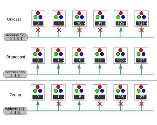
unique addresses and three addressing modes.
Unicast - only SADs with this address
will accept the received packet
Group - each SAD has two group addresses
which are derived from its Unicast address. It will accept any packet
addressed to either of its group addresses.
Broadcast - all SADs will accept the
received packet
Group Addressing Explained
Group addressing allows a single serial
packet to transfer colour data and commands to multiple SADs. How
useful this is depends on the specific application, however, with some
thought into the physical arrangement of the SADs group addressing can
enable very efficient control of the SADs using a minimum of packets.
Address mode
Address Value
Unicast
0 to 127 (range)
Group Row 0
128 (0x80)
Group Row 1
129 (0x81)
Group Row 2
130 (0x82)
Group Row 3
131 (0x83)
Group Row 4
132 (0x84)
Group Row 5
133 (0x85)
Group Row 6
134 (0x86)
Group Row 7
135 (0x87)
Group Column 0
144 (0x90)
Group Column 1
145 (0x91)
Group Column 2
146 (0x92)
Group Column 3
146 (0x93)
Group Column 4
148 (0x94)
Group Column 5
149 (0x95)
Group Column 6
150 (0x96)
Group Column 7
151 (0x97)
Group Column 8
152 (0x98)
Group Column 9
153 (0x99)
Group Column 10
154 (0x9A)
Group Column 11
155 (0x9B)
Group Column 12
156 (0x9C)
Group Column 13
157 (0x9D)
Group Column 14
158 (0x9E)
Group Column 15
159 (0x9F)
Broadcast
255 (0xFF)
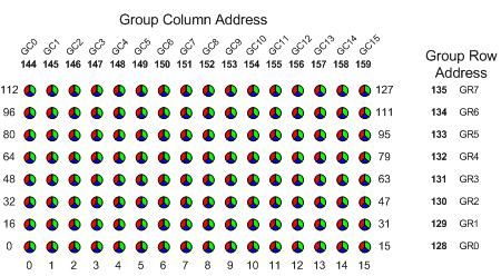
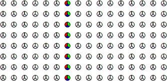
Group addressing
is based on the SADs being arranged into a grid as shown in the
illustration below.
This gives:
8 group rows with 16 SADs in each
row
16 group columns with 8 SADs in each column
It can be seen
that Group Row 0
includes 16 SADs with consecutive unicast addresses in the range 0
to 15.
Group Column 0
includes 8 SADs with unicast addresses 0, 16, 32, 48, 64, 80, 96, 112.
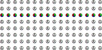
The examples below show
how a single packet sent to a group address is accepted by all SADs in
the group.
A packet sent
to Group Row 5 will be accepted by the SADs highlighted below
A packet sent
to Group Column 6 will be accepted by the SADs highlighted
below
Note: When the SAD is first powered on
after being programmed with the .HEX code it will initialise the EEPROM and set
the Device Address to 0
Frame 7 is a checksum value for the whole
packet. The checksum is calculated as the two's complement of the sum
of Frames 1 to 6 modulo 256. When a packet is received by the SAD
the checksum is added to the sum of the previous 6 frames. If the modulo 256
result is zero the packet is deemed to be good and will be processed.
If it is not zero the packet is discarded.
Example's of how to calculate the checksum
for data being sent to the SAD.
14 bit PIC Assembler
movfw
Frame1 ;
Load Frame 1 in to W
addwf Frame2, W
; Add Frame 2 to W, ignore carry
addwf Frame3, W
; Add Frame 3 to W, ignore carry
addwf Frame4, W
; Add Frame 4 to W, ignore
carry
addwf Frame5, W
; Add Frame 5 to W, ignore carry
addwf Frame6, W
; Add Frame 6 to W, ignore
carry
sublw 0x00
; 2's complement of sum in W
movwf checksum
; save W to checksum
This data is latched but not immediately
sent to the PWM output. The latched data is only transferred to the
PWM output when a 'Colour Transfer command' is received.
This allows different colour data to be
sent to different SADs followed by a single 'transfer command' broadcast to
all devices to allow many devices to initiate a change simultaneously.
Data0
Data1
Data2
Data3
0 to 255
0 to 255
0 to 255
0 to
255
Data0
Red PWM value (range 0 to 255)
Data1
Green PWM value (range 0 to 255)
Data2
Blue PWM value (range 0 to 255)
Data3
Fade rate value (range 0 to 255)
A colour value of 0 corresponds to 0% PWM (off), and
255 to 100% PWM (on)
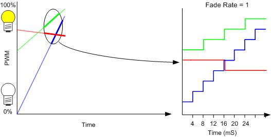
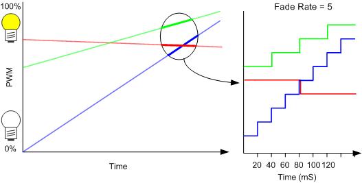
Fade rate value of 0 will cause the RGB
data to be transferred to the PWM output without fading.
Fade rate values from 1 to 255 are used
as a multiplier for the base fade rate step of 4mS. This is
illustrated below.
This data is latched but not immediately
sent to the Servo channel output. The latched data is only transferred to the
Servo channel output when a 'Servo Transfer command' is received.
This allows different Servo data to be
sent to different SADs followed by a single 'transfer command' broadcast to
all devices to allow many devices to initiate a change simultaneously.
Data0
Data1
Data2
Data3
0 to 255
0 to 255
0 to 255
0 to
255
Data0
Servo Channel 1 position (range 0 to 255)
Data1
Servo Channel 2 position (range 0 to 255)
Data2
Servo Channel 3 position (range 0 to 255)
Data3
Slew rate value (range 0 to 255)
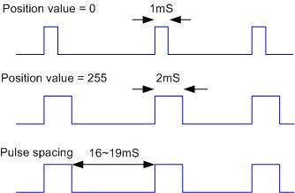
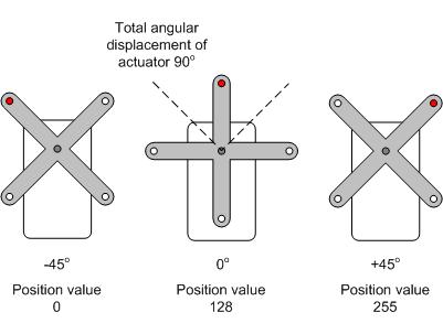
A position value of 0 corresponds to
a 1mS pulse (move CCW), and
255 to a 2mS pulse (move CW)
A position value of 128 corresponds to a 1.5mS pulse (servo 'home' or
centre)
Calculating position values
A = total angular displacement of servo
actuator
D = Position from centre, +/-degrees
Position Value = 128 + (256/A) x D
A = 90o, D = +10o
: 128 + (256 / 90o) x 10o = 156
A = 90o, D = -35o
: 128 + (256 / 90o) x -35o = 28
Minimum step angle = 256 / A :
90o / 256 = 0.35o
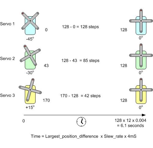
How autonomous slewing
works
A Slew rate value of 0 will cause the servo
position
data to be transferred to the Servo channel outputs. The servos
will move to their new positions at a rate determined by the specification
of the servo itself.
Slew rate values from 1 to 255 are used
as a multiplier for the base Slew rate step of 4mS. Once instructed to
move with a slew rate >0, the driver will gradually move all the servos to
their new positions autonomously.
The time taken to move is determined by the
angle moved and the slew rate:
a) full range move using minimum slew rate 1 requires (4mS x 1 x 255 ) =
1.02s
b) full range move using maximum slew rate of 255 requires (4mS x 255 x 255
) = 260s
If you send a slew rate > 0 to the Driver,
it will gradually move each servo from its current position to the new
position. The Driver calculates individual step rates for each servo
so that all three servos will arrive at their new positions at the same
time. The servo with the largest change in position will move 1 step
every 4ms x Slew_rate and this determines the total time taken.
In the illustration below the slew rate is
12, Servo 1 has the largest change in position, requiring 128 steps to get
to the new position.
If Frame 1 of the received packet has the Type
value 0xFF then Frames 3-6 must contain a valid Command. Commands can be
sent to a Unicast, Group or Broadcast address.
The values for Data2 and Data3 of Command
packets are used along with the checksum to verify the integrity of the
command packet. If these values are not correct the packet will be
ignored. Data2 must be set to 1 and Data3 must be set to 0.
A keep-alive packet will restart the
serial data inactivity shutdown
timer. Normally a keep-alive command should be broadcast to ensure
all drivers remain active.
The RGB colour data and fade rate are
transferred to the PWM output. This command will only transfer new RGB
colour and fade rate data. If no new data has been received since the
last Transfer then the command is ignored.
If the Fade rate value is 0 then the RGB
values are sent to the PWM output without fading. For Fade rate values >0
the firmware executes a linear fade from the currently displaying RGB colour
to the newly specified RGB colour.
If new RGB and Fade rate data is
transferred before the current fade has completed, a new fade will start
from the point the current fade had reached.
A single transfer command sent to the
broadcast address will cause RGB data unicast to SADs over many packets to
be transferred to their respective PWM output drivers simultaneously.
Important
With the addition of support for an RC
Servo driver, the Colour and Servo drivers use a common data packet.
To help avoid accidentally sending colour data to a servo or vice-versa two
different transfer commands are used. To further avoid problems, if a
Colour driver receives a Servo transfer command it will assume any 'new'
data it has may not have been intended for it and discard it.
To summarise:
If a colour driver receives a Servo transfer command it will:
1. Discard any new data it may have received.
2. Ignore the transfer command.
The settings for SAD address, serial
bit rate (and the inactivity timer in the full version) are saved to the EEPROM (NVRAM). When the save has completed
the SAD resets itself and reloads the address and bit rate values from EEPROM. The save will typically take less than 15mS to complete and
the reset then follows immediately after.
If a Save command is received and either
the address and/or bit rate have not changed, the current settings are
re-written to the EEPROM followed by a reset.
After a save command, allow at least 4
seconds for the reset to initialise the SAD before attempting to send
further packets to the Driver.
The value in Data1 is verified to ensure it
is in the range 0 to 127. The new setting will not take effect
until a Save command is received. If more than one 'Change Driver
Address' packet is received then most recent address is used.
Data0
Data1
Data2
Data3
3
Address value between 0 and 127
1
0
Warning:
If a Change Driver Address command is sent to a Group or the Broadcast
address, all SADs or SADs in the group will accept and hold the new
address. If a save command is then sent to the Group or Broadcast
address all SADs will change to the new address. It is therefore
not advisable to send this command to a Group or Broadcast address.
It can however be useful to do this if the
address of a SAD is unknown. In this case, disconnecting all other
SADs from the bus and then sending the address change and save commands
to the Broadcast address allows a known address to be assigned to that SAD.
The value in Data1 is verified to ensure it
is within range. The new setting will not take effect until a Save
command is received. If more than one 'Change serial bit rate' packet
is received then most recent value is used.
Sending a 'Change serial bit rate' command
to the broadcast address, followed by a 'Save' command also to the broadcast
address will cause all SADs to change to the new bit rate.
Data0
Data1
Data2
Data3
4
Select serial bit rate (see table
below)
1
0
Data 1 value
Bit rate selected
Free
Version
Full
version
0
1200 bps
Yes
Yes
1
2400 bps
Yes
Yes
2
9600 bps
Yes
Yes
3
19200 bps
No
Yes
4
38400 bps
No
Yes
The free version of the firmware does
not support bit rates of 19200 or 38400bps
Note: When the SAD is first powered on
after being programmed with the .HEX code it will initialise the EEPROM and set
the Bit Rate to 9600bps.
This command allows the PWM output to be
shutdown without affecting the current RGB data or fade that may be in
progress. When a PWM shutdown command is received, the PWM output port
lines are held at 0% PWM. When a PWM enable command is received
the PWM output port lines will be driven with the current RGB values.
While the PWM output is shutdown the SAD can continue to receive new
colour data and commands, including fades.
If a Save command is issued while the PWM
Output is shutdown, when the SAD restarts the PWM output will be enabled.
This command enables or disables
the serial data inactivity timer. The setting will not take
effect until a 'Save' command has been sent.
When enabled if no valid packets
addressed to the SAD have been received in the previous 260
seconds (4mins20secs), the PWM outputs are automatically shutdown.
(valid packets include those sent to the broadcast and group
addresses as well as the SADs own address)
The timer is reset each time
a valid packet is received, if no data needs to be sent to the
SAD, sending a Command 0 'Keep-alive' packet will reset the timer.
If the SAD has shutdown, any
valid packet received by the SAD will reset the inactivity timer
and restart the PWM outputs.
This function is not supported
in the free version of the firmware and will be ignored if received
by the SAD
The Servo position data and slew rate are
transferred to the Servo channel outputs. This command will only transfer new
servo position and slew rate data. If no new data has been received since the
last Transfer then the command is ignored.
If the Slew rate value is 0 then the new
position
values are sent to the Servo channel outputs immediately. For
Slew rate values >0
the firmware executes a 3 channel linear slew which will cause all three
servos channels to move incrementally from their current position to their
new positions, arriving at the final position simultaneously.
If new Servo and Slew rate data is
transferred before the current move has completed, a new move will be started
from the current position of the Servos.
A single transfer command sent to the
broadcast address will cause Servo data unicast to SADs over many packets to
be transferred to their respective Servo output drivers simultaneously.
Important
With the addition of support for an RC
Servo driver, the Colour and Servo drivers use a common data packet.
To help avoid accidentally sending colour data to a servo or vice-versa two
different transfer commands are used. To further avoid problems, if a
Servo driver receives a Colour transfer command it will assume any 'new'
data it has may not have been intended for it and discard it.
To summarise:
If a servo driver receives a Colour transfer command it will:
1. Discard any new data it may have received.
2. Ignore the transfer command.
These three commands each move a
single servo channel to a specified position, the other two servo
channels are unaffected. These commands take immediate effect;
no 'servo transfer' command is used.
If a servo slew operation is
already in progress when a Position Servo command is received, the
specified servo will immediately move to the new position in the
command. The other servos will be unaffected and continue with
the slew.