|
|
Voltage
programmable simple logic device
and square wave signal
generator
|
|
Description
Here's another daft yet
interesting PIC12F675 idea I came up with. When I wanted to show
someone how logic gates worked I could only find a NAND gate which
wasn't very handy for demonstrating AND's OR's, NOR's and
ExOR's. I also wanted to have a play with the A/D converter on
the 12F675 so I came up with the idea of a PIC that could function as
a single 2-input logic element.
The logic function is
determined by an analogue voltage applied to the GPIO4 pin when the
device is first reset, it isn't sampled again after this so logic
can't be changed on the fly. The 3 MSBs of the A/D conversion
give eight distinct voltage levels that map to specific logic
functions. Six functions have been implemented; these are
2 input AND, OR and EXOR gates and their negated equivalents.
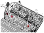
Just to prove the
concept, here is a 'D'
type flip flop (PIC Flop:-) I built out of five 12F675 Logic
Elements operating as NAND gates. The sixth device is configured
to operate in square wave mode to provide a clock input to the
flip-flop for testing. The small pushbutton provides the 'data'
input.
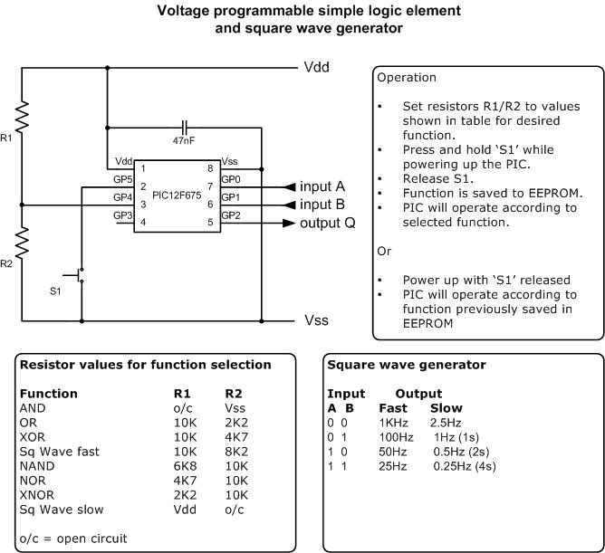
Square wave generator
With 8 analogue voltage levels and only six logic functions, this left
two unused functions so these have been used to provide a square wave
generator. There are two modes, fast and slow selected by the
voltage on the function select pin. Once selected the program
reads the data on inputs A and B and sets the frequency on the output
pin according to the table below.
This is read each cycle so the frequency can be adjusted during
operation.
B A Freq'
0 0 1KHz, 2.5Hz
0 1 100Hz, 1Hz (1s)
1 0 50Hz, 0.5Hz (2s)
1 1 25Hz, 0.25Hz (4s)
Selecting the
Function
When the device is first
powered up it reads the logic level on GPIO5. If the input is
low, the analogue voltage on GPIO4 is sensed and the logic function
determined as described above. The function selected is then
saved to EEPROM. If
the GPIO5 input is high when the device is powered up, the previously
saved function is read from the EEPROM and used. In this case
the analogue voltage on GPIO4 is ignored. This allows the function
that the PIC will perform to be selected once and saved so it can be
used repeatedly without having to set it each time the PIC is powered
on.
| Function value |
Function |
Voltage select |
| 0 |
AND |
GP4-Vss |
| 1 |
OR |
Vdd-10K-GP4-2.2K-Vss |
| 2 |
XOR |
Vdd-10K-GP4-4.7K-Vss |
| 3 |
Square Wave fast |
Vdd-10K-GP4-8.2-Vss |
| 4 |
NAND |
Vdd-6.8-GP4-10K-Vss |
| 5 |
NOR |
Vdd-4.7K-GP4-10K-Vss |
| 6 |
XNOR |
Vdd-2.2K-GP4-10K-Vss |
| 7 |
Square Wave slow |
Vdd-10K-GP4 |
Floating Inputs
The
inputs on pins GPIO0, 1 and 5 have the weak internal pull-up feature
enabled so no external pull-up resistors are required.
Selecting
function during device programming
If
your programmer supports writing to the EEPROM at program time, you can
set up the function when the code is programmed into the PIC. This
avoids the need to 'user program' the function with an analogue voltage on
first use. To do this you need to set the first three memory locations in
the EEPROM as follows: (see Source Code)
| Address
00 |
function from
0x00 thru 0x07 (see table above) |
| Address
01 |
0x81 -
validation byte |
| Address
02 |
0x69 -
validation byte |
If the validation bytes are
not correct, the EEPROM will be initialised and the function set to 0
Code and schematics
This code is written to work
on a 12F675 device. The HEX file below is assembled for and has been
tested with the 12F675. It should work on a 12F683 too but I haven't tried
it. This code won't work with a 12F629 because it doesn't have the ADC
feature.
Propagation delay
The code to emulate each
logic function takes between 6 and 9 instruction cycles to execute.
This makes the effective propagation delay between an input change and
the output response around 6-9 micro seconds using the 4Mhz internal
oscillator. While this is very slow compared to TTL logic for
example, it's still quite practical for low speed circuits. In
theory it should work up to about 100Khz. - I haven't tested it to
this speed though.
Aside from the logic
function I've found the square wave generator very handy to have when
experimenting with circuits on a breadboard. If you dig into the
source code you can tune the frequencies to suit your own needs.
The original version of
this was application was written in May 2004.
It doesn't have the save
function to EEPROM feature and the code to implement the logic has an
effective propagation delay of about 16 instructions (16 micro seconds
@ 4Mhz clock). It also doesn't enable weak pull-ups on the inputs.
I rewrote the code
because the square wave function is quite handy when developing
projects but having to have the resistors was a pain when working on
the bread board so I added the programmable functionality to the code
and took the opportunity to speed up the logic functions.
The original code is
available here but I recommend you use the version 2 code above.
Notes:
-
If you want multiple gates of the
same type you only need one resistor network to set the voltage level
and this can then be fed to several PICs in parallel since the input
impedance on the A/D converter is quite high.
-
In case it isn't obvious the
propagation delay between input change and output will be in the order
of 16uS so it's not going to replace high speed logic, but it does
work really well as intended; for educational and teaching purposes in
low speed circuits.
-
One
other point to be aware of, PIC's don't like their inputs left
floating so drive it or tie it but don't float it. The
version 1 code doesn't enable weak internal pull-up on the inputs
so this is important.
Contact us:
 |