|
LED Chaser
for PIC16F84A and 16F628A
|
 |
Description
This simple circuit functions
as a 12 LED chaser. A single illuminated LED 'walks' left
and right in a repeating sequence, similar to the effect seen on
KITT, the car in the
Knight Rider TV series.
Fully commented source code and
programmer ready HEX files are provided for the PIC 16F84A and
16F628A at the bottom of this page.
The circuit has been
constructed on a PCB but can easily be built on strip-board, or a
solderless breadboard.
This project has been put
together for anyone starting with their first PIC and the source
code is heavily commented with references to the PIC datasheets
and the MPASM assembler user guide.
Although the PIC 16F84A is
really obsolete and I wouldn't normally do a project using it,
this chip is used extensively throughout education and for many
people this will still be their first step into the world of
PICs. I've also written a version for the PIC16F628A which
is a pin compatible replacement for the 16F84A and I would
recommend that if you intend to develop your interest in PIC
microcontrollers you start using this device rather than the
16F84A.
Please note that the 16F84 and
16F628 without the 'A' suffix
are not suitable for this
project. You must use the 16F84A or 16F628A parts.
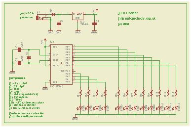
Schematic
Download
schematic in PDF

Circuit Description
The heart of the LED chaser is
the PIC microcontroller, IC1. This can be either a
PIC16F84A or PIC16F628A as software code is provided for either
device. The program that runs on this chip controls the LEDs
attached to the output port pins. Resistors R1 thru R12
limit the current through LED1 - LED12 to a safe level that
won't damage the PICs I/O ports or LEDs.
The value of the resistors has
been selected to be safe rather provide maximum brightness.
If you decide to use high brightness blue, green or white 5mm
LEDs you may need to change these from 270ohms to 100ohms.
For all other 5mm LEDs the 270ohm resistors will be fine.
Crystal Q1 and capacitors C1
and C2 connect to the oscillator circuit inside the PIC. This
generate a stable 4Mhz clock which is used by the PIC to control
the timing of the microcontroller core. If you are using
the PIC 16F628A you can omit these three components and use the
PICs internal RC oscillator. However, you will also need
to make a change to the source code before programming the PIC
so it knows to use it's internal oscillator.
(see here)
Capacitor C3 is used to
decouple the 5 volt power supply rail. If you are building the
circuit on a breadboard or stripboard you should ensure it is
located close to the PICs Vdd connection (pin 14 ).
The input voltage can be
anywhere form 9 to 12 volts but the PIC requires a precisely
controlled 5 volt supply. This is provided by IC2, a 78M05
3-terminal 5 volt regulator. Capacitor C4 decouples the input to
the regulator. Diode D1 protects the circuit from
accidental reverse polarity of the input voltage.
PCB Layout
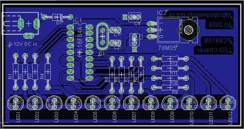
Download PCB
artwork in PDF
Download Eagle 5.02 CAD Files (ZIP)
Component List
You can buy all the parts
needed to build this project from most component suppliers world
wide. In the UK you can get everything from
Rapid Online and
I've included a parts list with their part numbers below.

All
Rapid parts/descriptions correct at 04-Sept-2008. You should
check part# and descriptions are correct when ordering in case
I've made a mistake transferring them onto this page.
Quick Order Parts list
 to use with the
Rapid cut & paste order form on their home page.
to use with the
Rapid cut & paste order form on their home page.
| Component |
Description |
Part # |
| R1 - R12 (order 1
pack) |
PK 100 270R 0.25W CF
RESISTOR (RC) |
62-0356 |
| C1, C2 (order 2) |
22PF 2.5MM PITCH
CERAMIC CAPACITOR RC |
08-0046 |
| C3 |
100N 5MM PITCH CERAMIC
DISC CAPACITOR RC |
08-0235 |
| C4 |
220NF 63V 5MM
POLYESTER BOX CAPACITOR RC |
10-3264 |
| Q1 |
4.00MHZ HC-49/S
CRYSTAL +-20PPM (RC) |
90-3254 |
| D1 |
1N4001A 1A 50V
RECTIFIER DIODE (RC) |
47-3420 |
| IC2 |
L7805CV +5V 1A VOLTAGE
REGULATOR (ST) RC |
47-3290 |
| LED1 - 12* (order 12) |
L-7113ID LED 5MM RED
DIFF 45MCD (RC) |
55-0155
|
| J1 |
2.1 PCB DC POWER
SOCKET (RC) |
20-0970 |
| socket for IC1 |
18 PIN 0.3IN TURNED
PIN SOCKET(RC) |
22-1723 |
| IC1** |
PIC16F84A-04/P
MICROCONTROLLER (RC) |
73-2634 |
| IC1** |
PIC16F628A-I/P (RC)
|
73-3340 |
| Power supply
*** |
9V 600MA MINI PLUGTOP
SW MODE PSU RC |
85-2957 |
Parts List Notes
* You can use almost any type of 5mm standard LEDs
of any colour with this circuit. If you
use blue LEDs you may need to change R1-12 from 270R to 100R.
**
use either PIC16F628A or PIC 16F84A
***
If you don't have a power supply, this one should be
suitable.
PIC Programmer
You can also buy the PICkit2 starter kit from Rapid, part #
97-0101
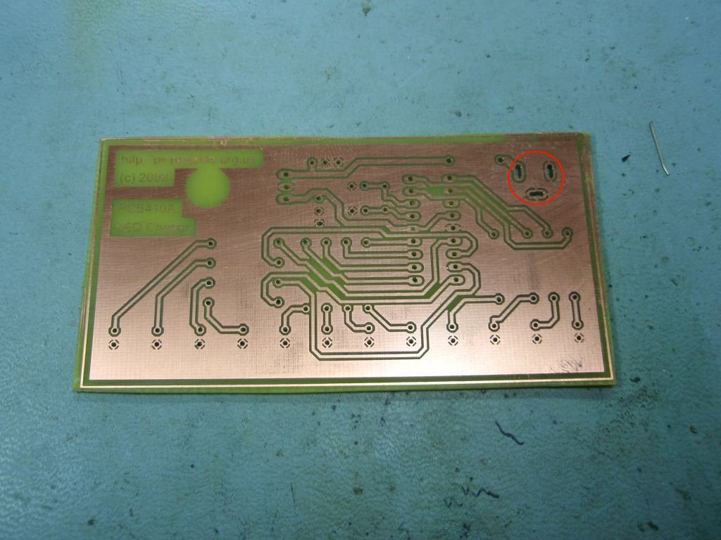
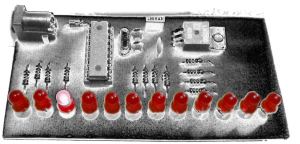
Construction notes:
In Fig 1. note how the holes
for the DC Power Jack (top right) have been milled into slots to
accept the solder tabs on the connector.
The photo shows PCB410A, the
artwork and Eagle files on this page are for PCB410B. I've
made some minor changes to the copper layout to make it easier
to solder the LEDs but the component placement remains
unchanged.
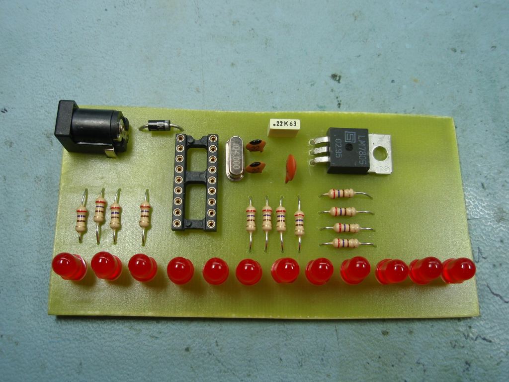
Fig. 2 shows the board with the
4Mhz crystal and capacitors fitted. This board will work
with the firmware on this page without modification.
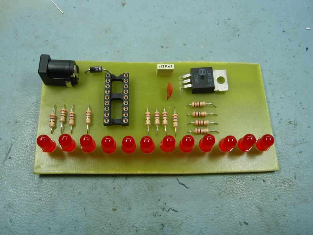
In Fig.3 crystal Q1, and
capacitors C1, C2 have been omitted. If you are using a PIC 16F628A you can use the
PIC's internal RC oscillator, in which case
you don't need to fit these components. If you do this you
will need to edit the 'ledchaser16F628A.asm' file.
Locate the line that says:
__CONFIG _CP_OFF & _WDT_OFF & _PWRTE_ON
& _HS_OSC & _LVP_OFF
and change it to:
__CONFIG _CP_OFF & _WDT_OFF
& _PWRTE_ON & _INTRC_OSC_NOCLKOUT & _LVP_OFF
You will then need to
reassemble the file. If you have installed the
Microchip MPLAB IDE software, you can load the asm file and then do a Project -
Quickbuild to create the HEX file. Once you've done
this, program the 16F628A with the new
ledchaser16F628A.HEX file.
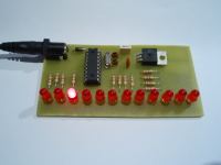
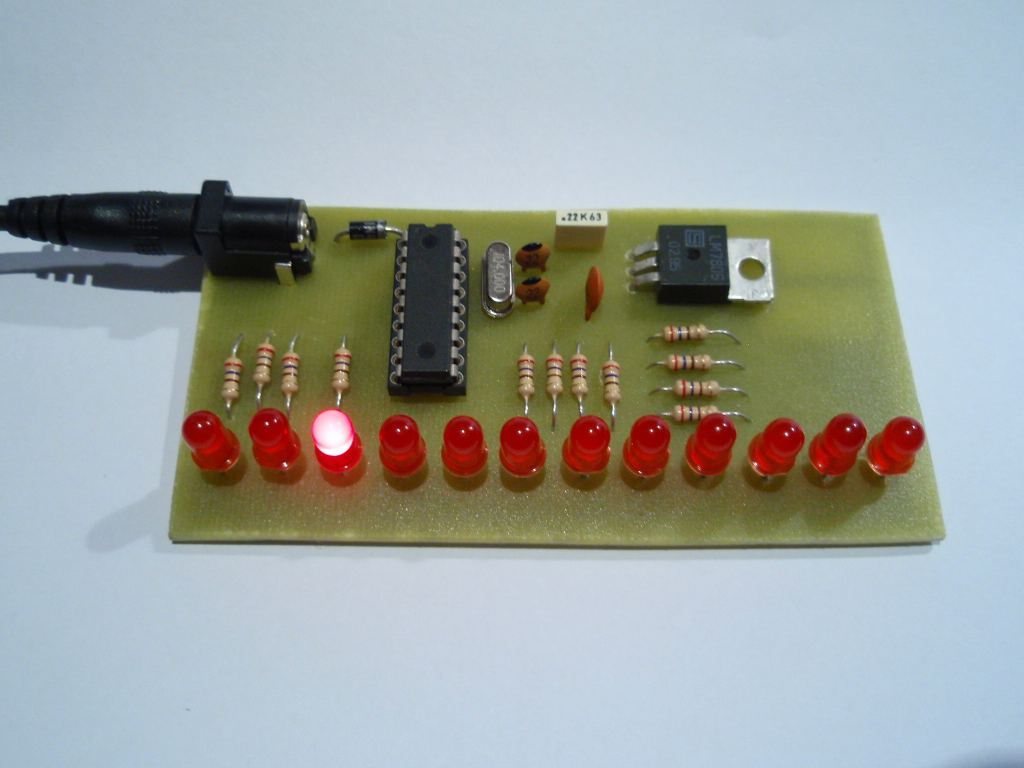
Fig. 4 shows the board
running the LED Chaser program.
Power Supply
The board includes a 5 volt
regulator and reverse polarity protection diode on board.
You will need to use a suitable DC power supply rated between 9
and 12 volts and able to supply at least 200mA.
In the UK you can buy a suitable power supply from Rapid Electronics.
The part number for this is included in
the component listing above should you not already have
something available.
Firmware
You can use either a PIC 16F84A
or PIC 16F628A microcontroller with this circuit. Download
the files required below.
The HEX files are ready to
program straight into the PIC. The asm files are the
source code which you can modify or just view to see how it
works. If you are going to modify the code I recommend you
download and install the
Microchip MPLAB IDE which will allow you to edit, modify and
program the PIC seamlessly.
If you need a PIC Programmer I
strongly recommend the
Microchip PICKit 2,
this is available from suppliers world wide or direct from
Microchip. It's reasonably cheap to buy and reliable.
I have a couple of them and I wouldn't use anything else now.
|
Description |
Filename |
Download link |
| Source
code for 16F84A |
ledchaser16F84A.asm |
download |
| HEX file
ready to program into the PIC |
ledchaser16F84A.HEX |
download |
| |
|
|
| Source
code for 16F628A |
ledchaser16F628A.asm |
download |
| HEX file
ready to program into the PIC |
ledchaser16F628A.HEX |
download |
| |
|
|
|
Microchip MPASM User Guide |
33014J.pdf |
download |
|
16F628A datasheet |
440044b.pdf |
download |
|
16F84A datasheet |
35007b.pdf |
download |
As noted elsewhere, the code
above will
not work with the non 'A' suffix parts. While the changes
to make it work are minor, I haven't tested them and therefore I
will only support it when used with the 16F84A / 16F628A.
Also be aware that the PICkit2 programmer does not support the
16F84 but it does support the 16F84A.
Contact us:
 |