|
F1 Gantry Race Start Lights Controller
How to modify the timing data
The timing data and mode parameters are
stored in the EEPROM data memory of the PIC microcontroller. This can be
edited and reprogrammed by the end-user to customise the parameters to
suit a specific application.
You will need a PIC programmer to read
and reprogram the PIC16F684 microcontroller. I recommend the
Microchip PICkit2 using the stand-alone application software. This
has been used in the guide shown below.
 Important:
Since the PIC microcontroller used
in the F1 Gantry Race Start Lights project has the Program Memory code protected it
is important that you DO NOT write the program memory area when writing
data back to the EEPROM.
By default it will overwrite the program memory unless you uncheck the
Program Memory Enabled option.
Step 1
Remove the PIC microcontroller from the
control board and place in the PICkit2 programming adapter, (
if you don't have one see here for details of
how to make one)
Step 2
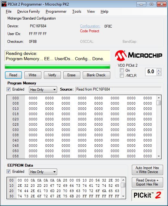
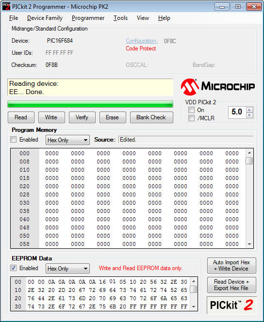
Click on the 'Read' button. When
it has finished reading the PIC you should see something similar to the
screen-dump below.
Note that:
- Device is a PIC16F684
- 'Code Protect' is shown in red
- The Program Memory contains all
'0000'
- Source shows 'Read from
PIC16F684' so we know the data has been read out of the PIC
- 'Program Memory' check box
is Enabled - This should be unchecked before writing back to the
PIC.
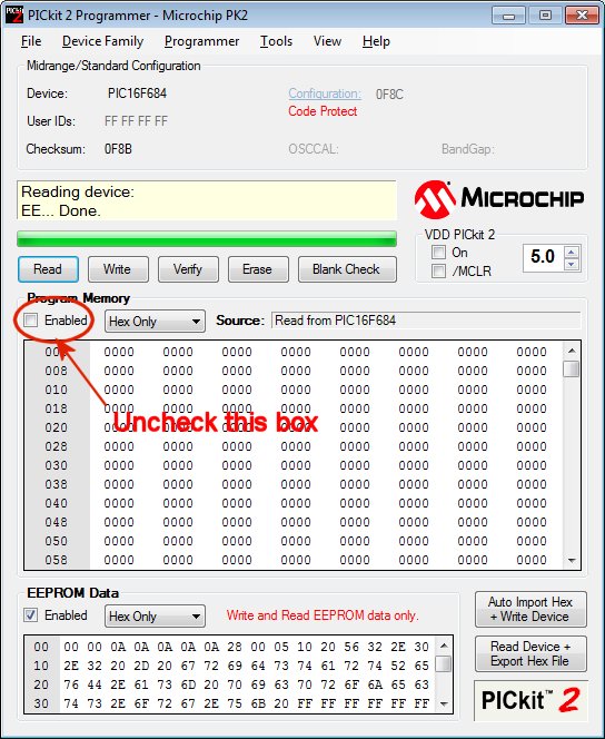
Step 3
Uncheck 'Program Memory' enabled check
box.
It is important that this is disabled
otherwise when the modified EEPROM data is written back, it will erase
the Program Memory area. If this happens, you will need to return
the PIC to us for reprogramming as it will no longer work.
Step 4
You can now edit the data in the EEPROM
Data window. From August 15th 2012 kits ship with V4. firmware
- The parameters that can be changed
are shown below. An example of edited timing data is show in
the next step.
- The values entered in the EEPROM
Data window must be in hexadecimal. (see Decimal /
Hexadecimal Numbers section below if you don't know what this means)
- If you mess up at this point you
can go back to Step 2 and read the EEPROM again to clear any
changes you have made.
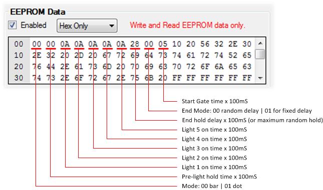
Firmware V3. EEPROM example
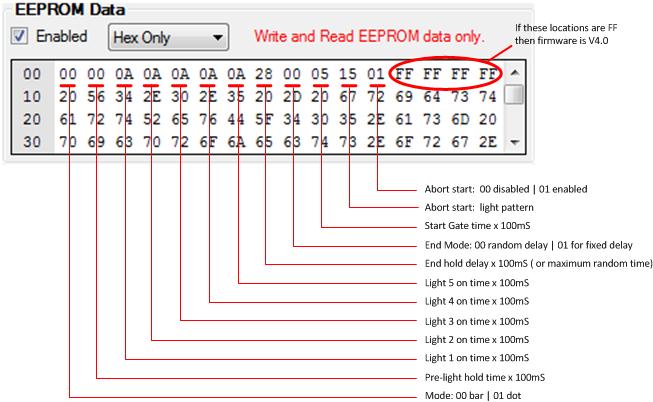
Firmware V4. EEPROM example
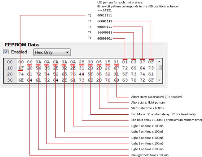
Firmware V5. EEPROM example
Decimal / Hexadecimal Numbers
If you don't understand
hexadecimal, use Google to do the conversion for you. In the
example below we want to convert 160 to a hexadecimal. The
result is shown as 0xA0. You ignore the 0x part and use the
last two digits for the EEPROM Data, in this example it would be A0

The largest decimal number that
can be used in the timing data is decimal 255 (hexadecimal FF)
Parameters that can be modified
The table below is copied from the main
project page for continuty.
Modes and
Timing

|
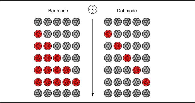
Display modes
The outputs can operate in
either bar or dot mode. |
 |
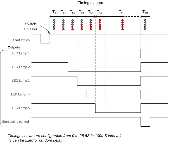
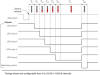
| Timing Data
The timing diagram shows
all the parameters that can be configured. These can
be set from 0 to 25.5 seconds in 100mS intervals
Default timings shown as
decimal and (hex)
supplied in the kit.
0 (00)
; light mode value, 00 bar | 01 dot
0 (00) ; pre-light hold time value x 100mS [TP]
10 (0A) ; light 1 on time value x 100mS [TL1]
10 (0A) ; light 2 on time value x 100mS [TL2]
10 (0A) ; light 3 on time value x 100mS [TL3]
10 (0A) ; light 4 on time value x 100mS [TL4]
10 (0A) ; light 5 on time value x 100mS [TL5]
40 (28) ; end hold delay value x 100mS (or maximum random time) [TH]
0 (00) ; end mode: 0 for random end delay | 01 for
fixed end delay
5 (05) ; start gate output time value x 100mS [TSTC]
This gives 5 lights
illuminating in bar mode at 1 second intervals with a 0-4
second random delay at the end. Start gate output is
active for 0.5S |
 |
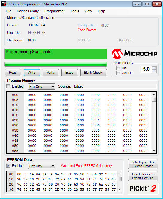
Step 5
The screen shot below shows the EEPROM
Data with two values changed. This is an example and you can of
course edit all the timing parameters to suit your application.
- the 'End hold delay' value from 28
to 16.
16 equals 22 in decimal so the end hold value is now 22 x 100mS =
2.2S
- the 'End hold mode' value from 00
to 01.
This changes the mode from a random end delay to a fixed delay; in
this case it will be 2.2 seconds since we also changed the 'End hold
delay' value.
Note that:
- Source is showing as 'Edited'
This is because the EEPROM data has been changed from that read back
from the PIC in Step 2.
- In the EEPROM Data section it
shows 'Write and Read EEPROM data only'.
This is showing because 'Program Memory enabled' has been
unchecked.
Step 6
When you have edited the EEPROM data to
suit your application you can reprogram the PIC by selecting the Write
button.
Make sure that the 'Program Memory enabled' check box is UNCHECKED before
clicking on the Write button - hopefully you're getting the message :-)
Once the PIC has been reprogrammed it
can be installed back in the control PCB and tested.
Contact us:
 |