|
|
binary/bcd to
7-segment decoder
for PIC16F627A /
16F628A
|
 |
Overview
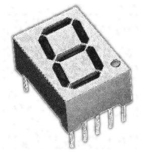
This is a building block project I
developed to try out a few ideas. It decodes a 4-bit binary
word to outputs that will drive a 7-segment LED display. Functionality
it is similar to the
7447 BCD-to-seven-segment decoder/driver IC. However, because it's
implemented using a microcontroller, the segment control data can be
customised to display any set of 16 characters you wish to create.
It also has an 'invert' control input that allows it to drive either
common anode (active low) or common cathode (active high) LED
modules.
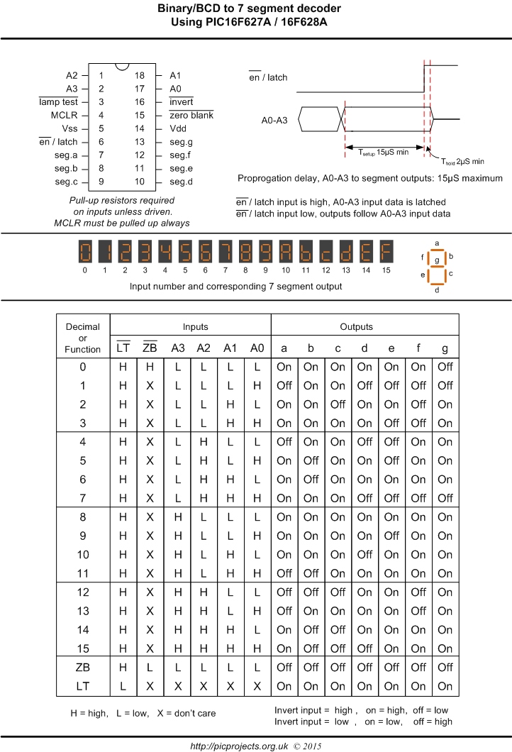
Binary/BCD or Gray to 7-segment decoder
- Depending on firmware:
- 4-bit binary input to
7-segment decode, 0-9, A-F
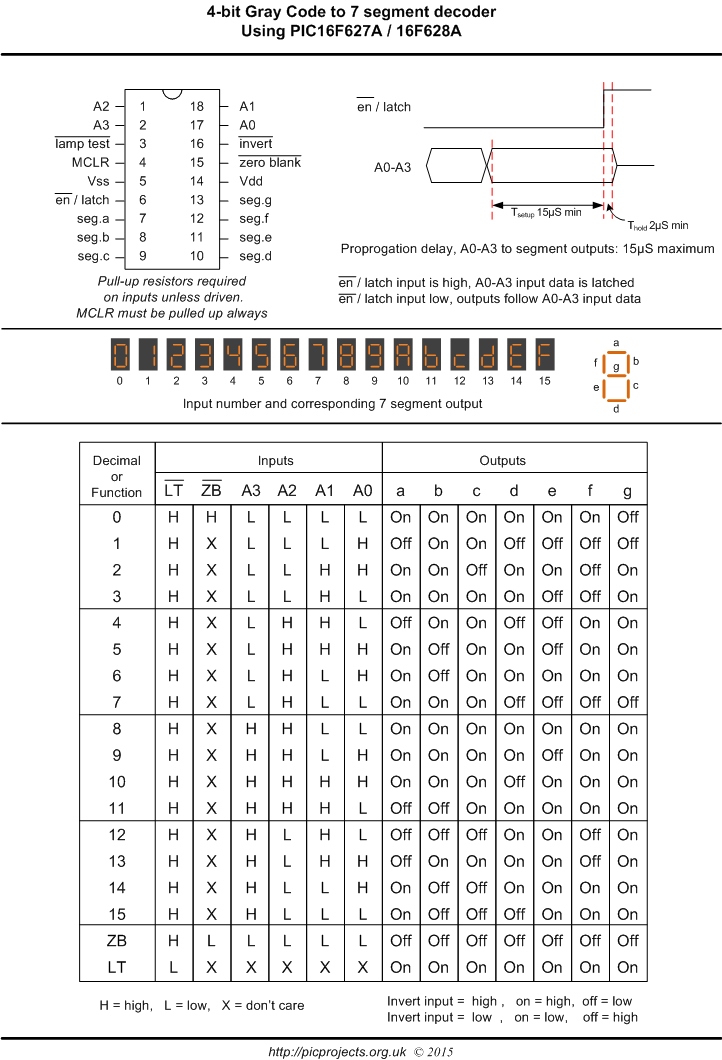
- 4-bit Gray input to
7-segment decode, 0-9, A-F
- Lamp test input
- Zero blanking
- output invert, allows use of
common anode or common cathode displays
- input latch
- Outputs rated at 20mA per
segment (Max)
Since the decoding is done with a
lookup table it is possible to map the binary input to any character
on the 7-segment display. There are now two variants of the
software available to download, the original 4-bit binary to
7-segment hex decoder and a 4-bit
Gray code to 7-segment hex decoder.
Video clip below shows the board I used to test
and develop the code. Actually I developed the code entirely using
the Oshonsoft
PIC simulator and only did final testing on real hardware. The 8 pin chip on the left side is a
PIC12F629 programmed to generate a 4-bit binary count. The
green LEDs show the binary input to the decoder which is running the
decoderBin.HEX firmware.
Decoder taking Gray code input (decoderGray.HEX firmware).
In this clip the 12F629 has been programmed to generate a 4-bit Gray
code output.
Schematic
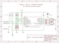
Demo / evaluation
schematic

The idea behind this project is
that the PIC can be used as a decoder for 7-segment LED displays and
therefore it will be built into some other application. The
schematic is provided for evaluation only. Since it uses a
binary hex rotary switch at the input make sure you use the
decoderBin.HEX file and not decoderGray.HEX
Note on the hex rotary switch type.
The hex rotary switch shown in
the schematic is an inverted or complimented output type.
That is the internal switches close for a binary 0 and open for
a binary 1.
If you use a normal/real output
type where the switches open for a binary 0 and close for a
binary 1 you would need to connect the switch common pin to +5v
and the four resistors to Gnd.
Description
Binary Decode
Datasheet
Gray Decode
Datasheet
Operation
The PIC use an internal clock
source so no external timing components are required, you will need
to fit a decoupling capacitor across the Vdd/Vss supply close to the
PIC; 100nF ceramic will do the job. The PIC microcontroller
requires a power supply voltage between 3 and 5 volts.
Inputs require an external pull-up
resistor unless actively driven by an external source. All unused inputs should be tied to
Vdd via a 4K7 resistors. The MCLR input (pin 5) is the
microcontrollers reset line and needs to be tied to Vdd via a
resistor (anything from 1K to 10K)
Because the decoder is implemented
in software running on the PIC, input to output propagation delay
can be up to 15uS from valid data appearing on the A0-A3 inputs to
the decoded data appearing on the 7-segment display outputs. Input data on A0-A3 should be held
and valid for 15uS before the
en/latch input goes high to ensure the correct input data is latched.
Outputs on the PIC16F627A / 628A
are rated at 25mA with a maximum of 200mA for all I/O pins.
This means it can drive a 7-segment LED display directly (via
current limit resistors).
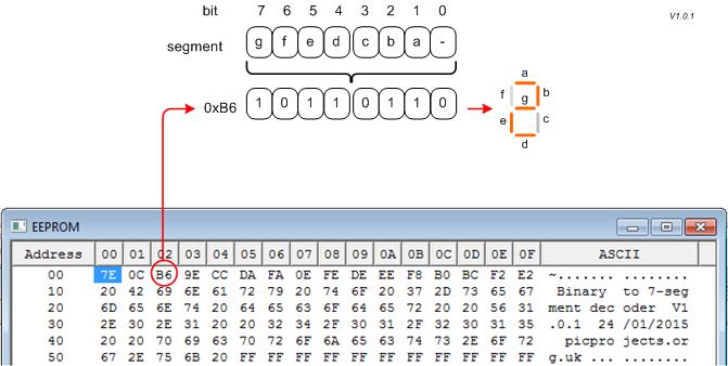
Customizing Segment Data
The segment data used to drive the
outputs is held in the EEPROM of the PIC making it easy to edit
without having to reassemble the source code.
The data is held at addresses 00 to
0F in the format shown below
Download
|
Description |
Filename |
Download link |
| Source
code for 16F627A / 16F628A |
decoder.asm
04/03/2013 |
 download
 |
HEX file
ready to program into the PIC.
Use with 16F627A or 16F628A |
decoderBin.HEX
04/03/2013 |
download
checksum 0x0A86 |
HEX file
ready to program into the PIC.
Use with 16F627A or 16F628A |
decoderGray.HEX
04/03/2013 |
download
checksum 0x0A86 |
Contact us:
 |
