|
UFO
round LED Chaser
with speed control
for PIC16F628A (#433K)
|
 |
Description
This is an updated version of
the UFO LED Chaser project, revised to use the PWM LED Chaser
code version 3.0.0 with support for variable chase speed.
The basic LED chaser 'engine' firmware is the same as that used with the 481/483 LED
chaser projects also on this site. The only difference is the
sequence data used to create the programmer ready .HEX file.
This has
been modified to include chase effects that suit the circular
arrangement of LEDs.
Unlike many simple LED chaser
projects the design presented here provides 8 LEDs
directly driven from the PIC along with a single mode control switch
and speed adjust control. The
firmware elsewhere on this page drives the LEDs with a
5 bit PWM signal providing each of the 8 LED channels with four
levels of intensity; off, dim, mid and bright.
A number of sequences are programmed into the firmware to
provide some interesting visual effects and chase sequences.
The software has sequential, random and manual sequence run
modes and manual advance to the next sequence in any mode.
The selected sequence and mode are also saved to non-volatile
memory so it will always restart in the selected mode.
The design is deliberately
simple with each LED being directly driven from a PIC I/O pin.
You can use it with different
sized LEDs and mixed colours. While it works well as a
simple LED chaser, thinking outside the box it can be used to add
effects to toys and models and even accessorize fancy dress
costumes. See FAQ
A solder pad jumper on the PCB
selects between fixed speed chaser using internal timing or
variable chase speed adjustable using the on-board variable
resistor. The adjustable chase speed option makes it
ideal for use in a wide range of applications. The kit
433K includes all parts needed to build the variable speed
chaser.
The firmware pre-programmed
into the PIC16F628A supplied with the kit includes over 34 chase
effects and sequences. If you're interested in PIC
micros and programming and want to modify the sequences or
create new ones, the source code and
programmer ready HEX file is provided at the bottom of this page.
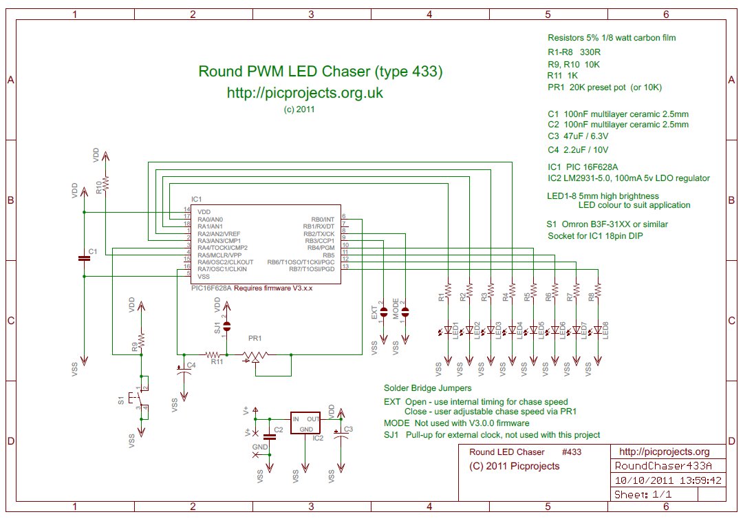
Schematic
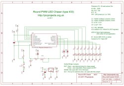
Download
schematic in PDF

Circuit Description
The heart of the LED chaser is
the PIC 16F628A microcontroller, IC1. The program that runs on this chip controls the LEDs
attached to the output port pins. Resistors R1 thru R8
limit the current through LED1 - LED8 to a safe level that
won't damage the PICs I/O ports or LEDs. Resistor R9
provides a pull-up for the input connected to switch S1.
R10 holds the PICs MCLR reset signal high.
The variable resistor PR1 along
with C4 are used to create a software oscillator. C4 is
charged and discharged via PR1 from port B0 output. The
input on Port A7 is monitored by the firmware, when the input
goes high port B0 is driven low to discharge C4. When Port A7
goes low, port B0 is driven high to charge C4. An
important requirement is the use of a Schmitt trigger input
buffer on Port A7 input pin which provides the
necessary hysteresis to make the software oscillator work.
This oscillator is then used to provide the clock for the chaser
timing and since the speed is controlled by the rate C4 charges
through PR1 the chaser speed can be controlled by adjusting
PR1. A 1K0 resistor, R11 is placed in series with PR1 to set the
maximum chase speed when PR1 is adjusted to minimum resistance.
Capacitor C1 is used to
decouple the 5 volt power supply to the PIC. If you're building the
circuit on a breadboard or stripboard you should ensure it is
located close to the PICs Vdd connection (pin 14 ).
Power is supplied to the
circuit via the +/- solder points. The voltage regulator,
IC2 is a LM2931-5.0, low-drop-out regulator and will maintain
regulation with an input voltage down to 5.8 volts. Input
voltage for the LED chaser should be between 6 volts and 14
volts to ensure power dissipation remains within limits.
The LM2931-5.0 regulator is designed for battery powered and
automotive applications and includes internal current limiting,
thermal shutdown, as well as reverse battery connection without damage to
itself or the circuit behind it. Capacitor C3 is important
and must be fitted to prevent instability of the regulator
output
Typical current drawn by the
circuit with all LEDs on is only around 80mA; with all LEDs off
it is under 5mA.
Notes:
- The latest
high brightness LEDs are very bright even with 330R current
limiting resistors. However, if you do need to change these resistors
for some reason take into account the maximum current
that the on-board voltage regulator can deliver is 100mA.
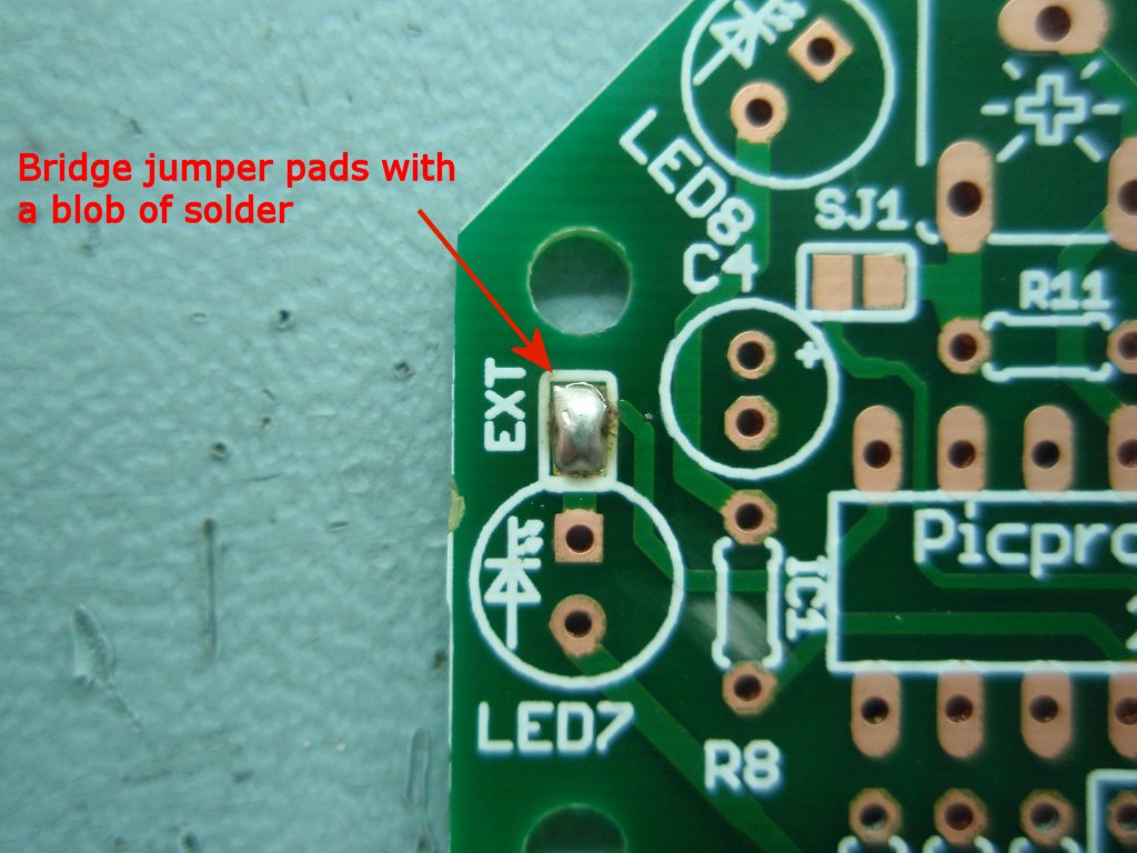
- EXT solder bridge
jumper.
When left open the chaser runs at a fixed speed using the
internal sequence timing data.
When closed (bridged with solder on the PCB) the chaser uses the software controlled
oscillator for timing, the frequency is adjusted using PR1
which in turn controls the chase speed.
If you leave the 'EXT' jumper open, you can omit PR1,
R11 and C4. The circuit and firmware will operate
correctly using the internal timing data.
- The jumpers marked 'SJ1'
and 'MODE' are not currently used. Do not
bridge them with solder.
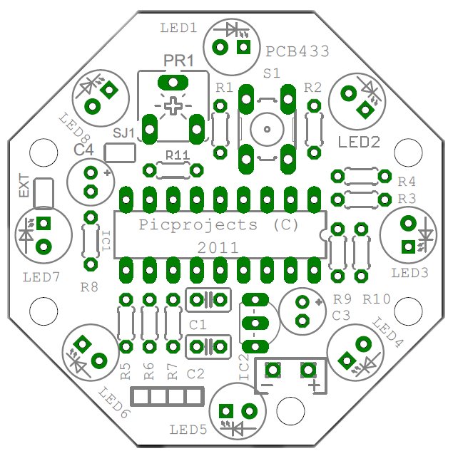
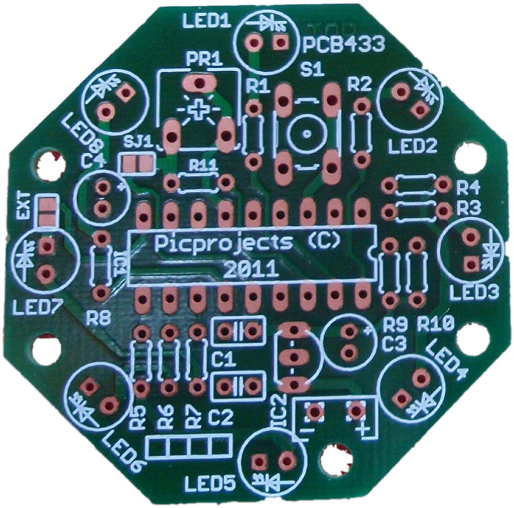
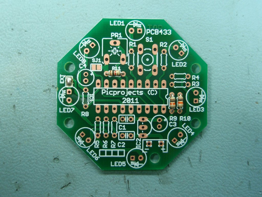
PCB Layout

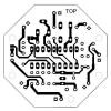
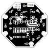
The PCB measures 48mm across the
flat faces
Four mounting holes are 3mm
diameter (use M3 screw)
Artwork for this board is not
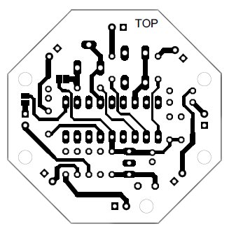
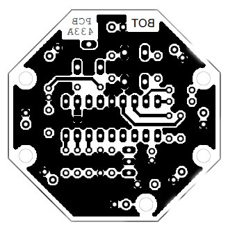
available since the double sided layout isn't really suitable
for home production.
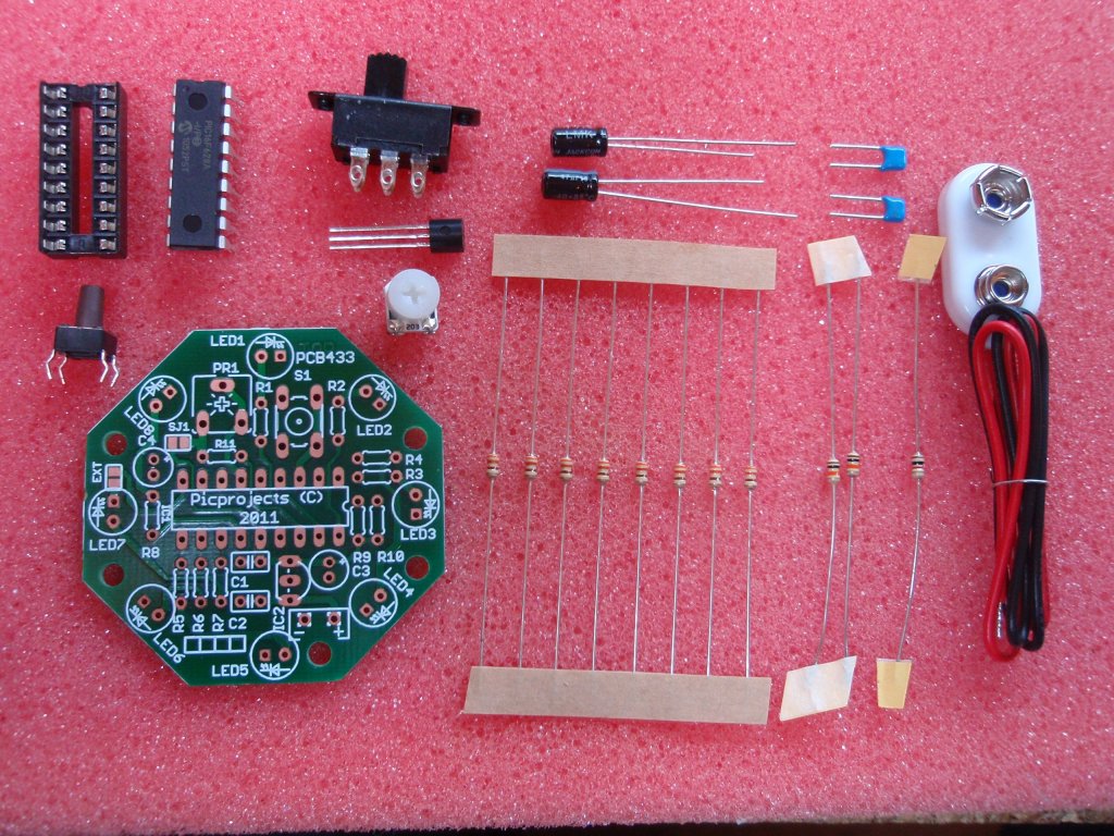
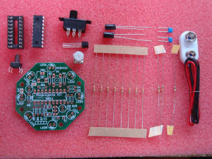
Component List
| Although
we're no longer selling the kit for this project we
still have stock of the PCB433 available.
Cost is £10 for 10 PCBs +
postage (we ship world wide)
email
pcb433@picprojects.biz if you're interested in buying.
Kit
Component list
| Label |
Description |
Qty |
| R1-R8 |
330R 5%,
0.125 watt carbon film |
8 |
| R9, R10 |
10K 5%,
0.125 watt carbon film |
2 |
| R11 |
1K0 5%,
0.125 watt carbon film |
1 |
| PR1 |
20K preset |
1 |
| C1,C2 |
100nF
multilayer ceramic (2.5mm) |
2 |
| C3 |
47uF
radial electrolytic |
1 |
| C4 |
2.2uF
radial electrolytic |
1 |
| IC1 |
PIC16F628A
(pre-programmed with firmware) |
1 |
| IC2 |
LM2931-5.0
LDO regulator |
1 |
| SW1 |
Tactile
switch (like Omron B3F-31xx) |
1 |
| SW2 |
sub-minature slide switch |
1 |
| C1 |
battery
connector + 150mm leads |
1 |
| SKT1 |
18 pin DIP
socket |
1 |
|
PCB433 |
Double
sided FR4, thru-plated, with solder mask, top overlay
and OSP finish. |
1 |
- Kit #433K does not
include the LEDs, these can be bought separately or
sourced independently.
- Kit #433KBL
includes 8 x 5mm high brightness blue LEDs
- The PCB is available to
buy on its own if you want to source the parts
and program the PIC yourself. (programmer ready
HEX file is free to download here)
|
Kit 433K

PCB Only (433P) |
| |
|
Construction notes:

- Follow
these instructions carefully.
- The PCB is
double sided, thru-plated which makes removal of incorrectly
installed components difficult without damaging the component
and/or the PCB.
- Pay attention to the
assembly instructions and make sure each component is fitted the
right way round and in the right position.
- Some
components need to be fitted the correct way round and
others look similar but have different values so must be
identified and fitted in the correct position.
- Check
twice, solder once :-)
click on the photo's for
1024x768 large version.

Fig.1 |
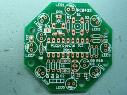
Fig .2 |
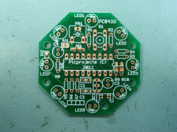
Fig. 3
|
|
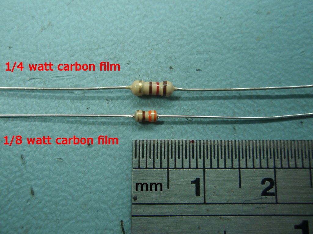
Fig 1. Start by bridging the solder jumper marked 'EXT' with a blob of
solder

Next
fit the resistors. There are 11 in total: 8 x
330R resistors, 2 x 10K resistors and 1 x 1K resistor.
The colour bands only
indicate the resistance value. Since resistors are
not electrically directional components it doesn't
matter which way round the resistor is fitted.
The resistors used here are 1/8 (0.125) watt parts which are about half the
size of standard 1/4 (0.25) watt resistors so the colour bands
are not so easy to see. If you buy the PCB only and are
supplying your own parts make sure to get 1/8 watt
resistors as the 1/4 watt ones are too big to fit on the
PCB.
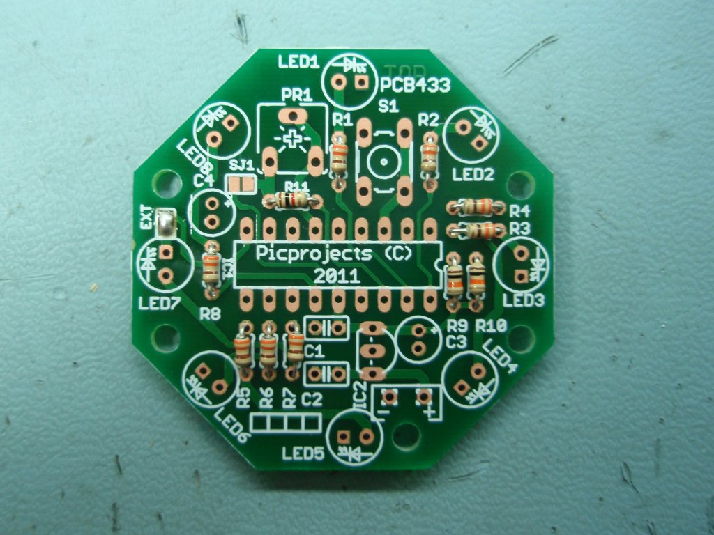
In Fig 2.
Fit the single 1K0 resistor to position R11
 [brown-black-red-gold]
In Fig 3.
Next fit the two 10K resistors to positions R9 and R10
 [brown-black-orange-gold]
|

Fig.4 |

Fig.5 |

Fig.6
|
|
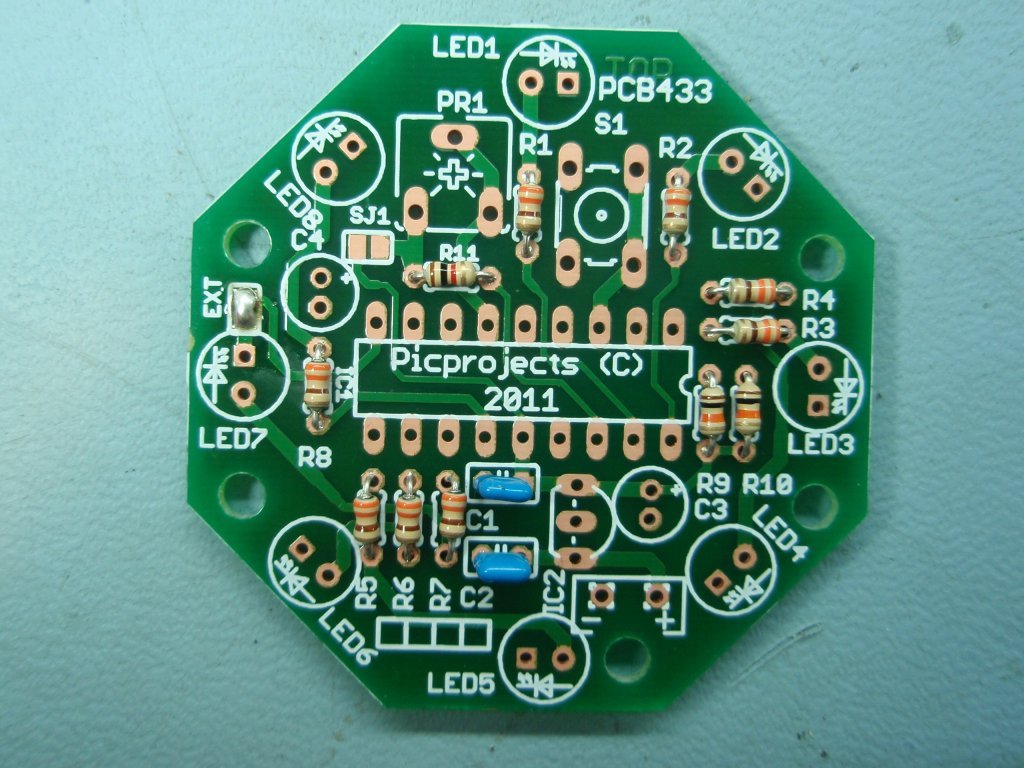
Fig 4. Finally
fit the eight 330R resistors to positions R1 to R8
 [orange-orange-brown-gold]
Resistor colour codes explained
Fig 5.
Next
fit the two 100nF capacitors C1 and C2. These are marked '104' on one side
(see photo right)
The package on these is
blue, it has no significance and may be any colour.
Fig 6. Fit
the 18 pin DIL socket to position IC1. You will see a small notch in
one end. It should be fitted so the notch is at
the same end as the small semi-circle marking on the PCB
overlay. Do not install the PIC16F628A into the socket
at this stage.
|
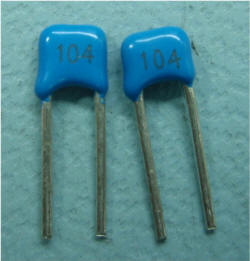 |

Fig.7 |

Fig.8 |
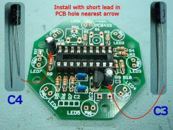
Fig.9
|
|
Fig 7. Next fit
IC2 (LM2931 LDO voltage regulator). This has three
leads and must be fitted the correct way round.
The body has a 'D' shaped profile when viewed from above
and it should be fitted so it matches the marking on the
PCB overlay
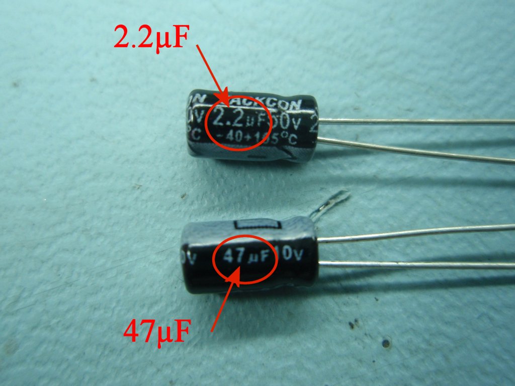
Fig 8. The two
electrolytic capacitors look very similar but have
different capacitance values so you will need
to inspect them to identify which one is which:
- C3 is marked 47µF
- C4 is marked 2.2µF
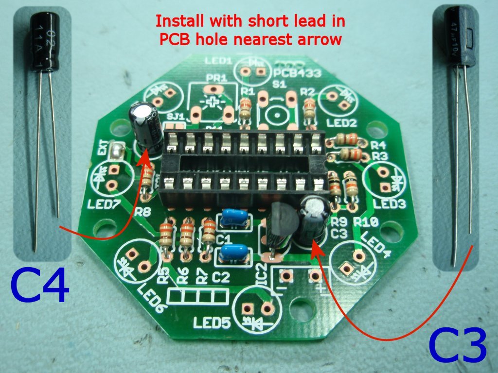
Fig 9. Capacitors C3 and C4
must be fitted the correct way round. You will see
that one of the leads is shorter. This is the negative terminal
of the capacitor. It must be located so the short
lead is in the hole towards the bottom edge of the PCB
as shown Fig 9. photo.
It is important that the correct value capacitor is
fitted in each location or the circuit will not operate
correctly.
|
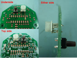
Fig.10 |
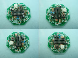
Fig.11 |

Fig.12 |
|
Fig 10. You now need
to fit the switch S1 and speed control resistor PR1. For
the construction notes I've mounted them both on the
component side, however these can be fitted to
either the
component side or the
solder side of the PCB. Which side you fit the
switch and resistor will depend on how you are going to
use the LED chaser and mount the
assembled board. The photo in Fig 10.
illustrates the different ways they can be fitted.
The leads on the switch are a tight fit. Position
the ends of the leads into the holes in the PCB, then
push with even pressure using the tips of your thumbs on
either side of the switch body. It should then snap into
place. Don't try and push it into place using the
button.
Fig 11. This photo shows the assembled board
from four different views. Your board should now
have all the components shown here assembled onto the
board.
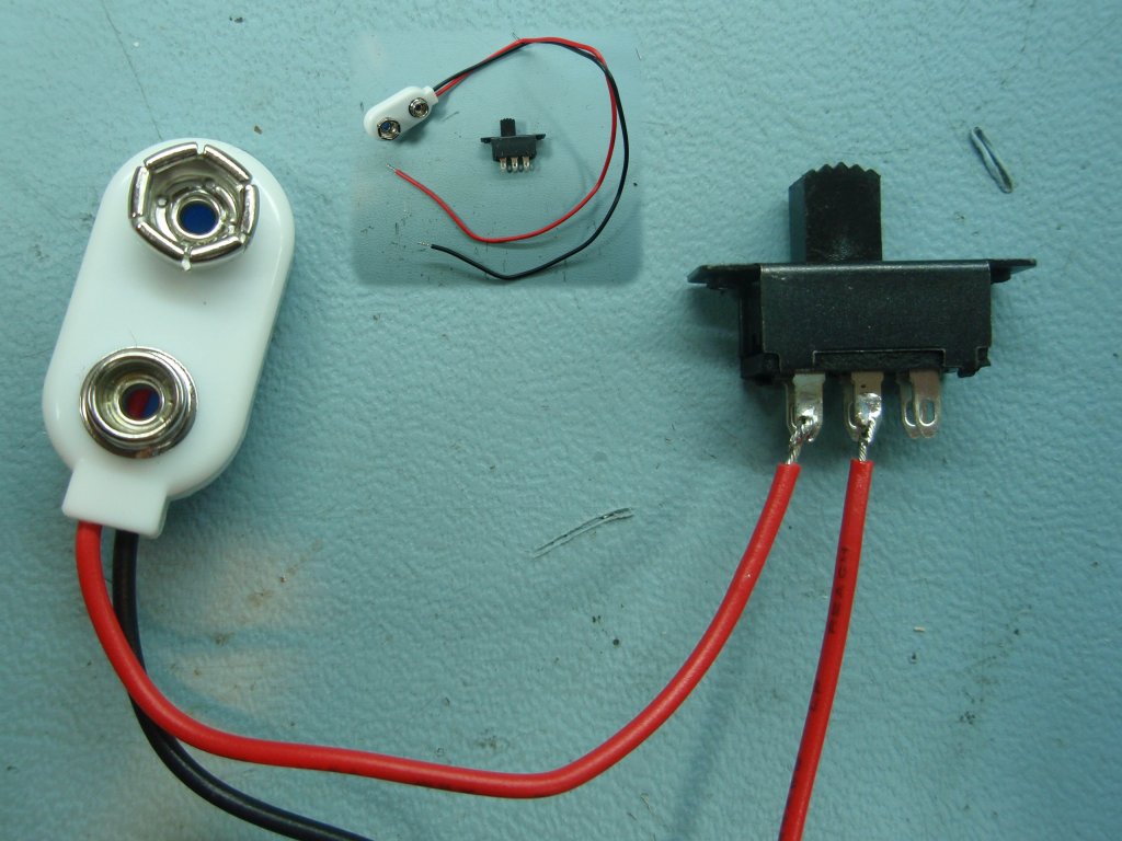
Fig 12. The switch in-line with the battery
connector is used as a power on/off switch.
Take the battery lead and the slide
switch. Cut the red wire about half way along its
length. Strip back about 7mm of
insulation from each end. Insert the bare wire
ends half way through the hole in the switch terminal
and bend back 180o. Now solder to the
terminal as shown in the photo.
The switch is a DPDT (double-pole, double-throw) type
with 6 terminals. Only two are connected for the on/off
switch function.
|

Fig.13 |
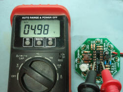
Fig.14 |
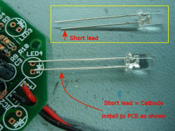
Fig.15 |
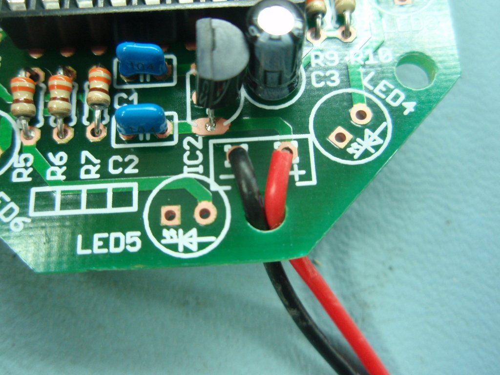
Fig 13. Solder
the battery connection lead to the solder points as
shown. There is a hole in the PCB; pass the
leads through this hole then insert into
the solder points (red to +, black to -). This
hole provides strain relief for
the wires.Fig 14.
[You
don't have to do this step if you don't have access to a
voltmeter, but it's worth doing if you can]
Check the underside of
the board to make sure the solder joints are good and
there are no shorts or solder bridges, resolder any
suspect joints and clean off the underside.
Apply
power to the board; the input voltage (at the battery
terminals) should be between 6 and 14 volts DC. A 9 volt
PP3 battery is ideal for this.
Measure the voltage
between pins
5 and 14 of the IC1 socket. IC2 regulates the
input voltage to a nominal 5 volts so it should measure
between 4.8 and 5.2 volts. If it doesn't
investigate why and correct the problem before
continuing with assembly.
Fig 15. You
can now solder the LEDs into position.
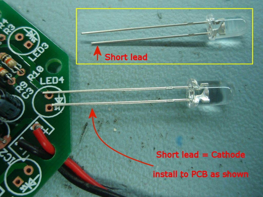
The LEDs must be installed the correct way round.
Each LED has two leads
and one lead will be shorter than the other. The short
lead normally indicates the LED Cathode terminal and
it must be fitted into the hole toward the arrow point
on the PCB overlay.
I have yet to see an LED where the short lead is not the
Cathode, however with so many suppliers of cheap LEDs
from China and South East Asia it is worth checking an
LED out-of-circuit before assembling them onto the PCB.
The
basic 433K kit is supplied without LEDs so
you will need to supply these yourself, or you can buy
them from the picprojects eShop. Kit 433KBL, also
available from the eShop includes 8 x 5mm high
brightness blue LEDs. |
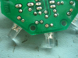
Fig.16 |

Fig.17 |

Fig.18 |
|
Fig
16. When soldering the LEDs to the PCB solder only
one lead of each LED to start with. Once all the
LEDs are fitted, adjust their position so they are
correctly aligned and pointing in the direction
required. Then solder the remaining leads to fix
the LED and complete the electrical connection.
If you solder both leads of each LED and then try and
move it you risk damage to the PCB and/or LED.
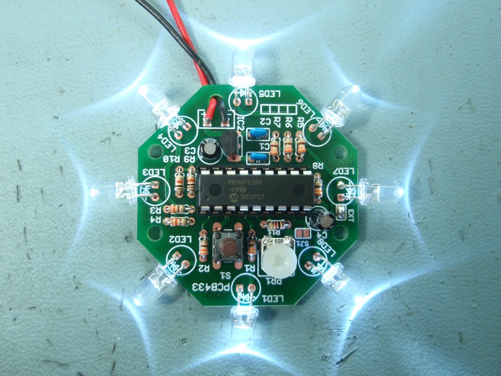
Fig
17. This
photo show the completed LED chaser. The LEDs
have been bent at a right angle to change the visual
effect of the chaser. The LEDs can also be mounted
vertically or even using short flexible wire fly-leads
if you are building it into a custom application.
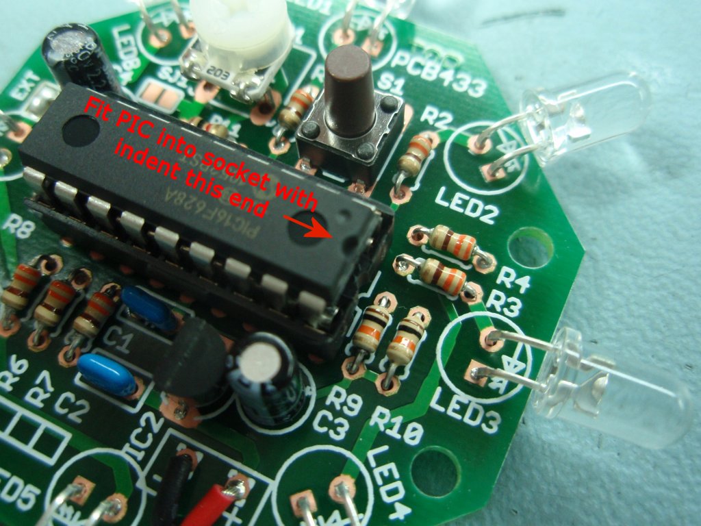
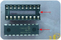 Fig
18. Finally you can fit IC1, the PIC 16F628A
microcontroller. The PIC has a notch in one end of
the device and assuming you have fitted the socket
correctly, the PIC should be inserted into the socket
with the notch in the PIC at the same end.
Referring back to Fig 18. the notch should be at the
right hand end as seen in the photo. Fig
18. Finally you can fit IC1, the PIC 16F628A
microcontroller. The PIC has a notch in one end of
the device and assuming you have fitted the socket
correctly, the PIC should be inserted into the socket
with the notch in the PIC at the same end.
Referring back to Fig 18. the notch should be at the
right hand end as seen in the photo.
Make sure the pins of
IC1 go into the socket and don't get bent underneath or
down the outside of the socket. |
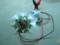

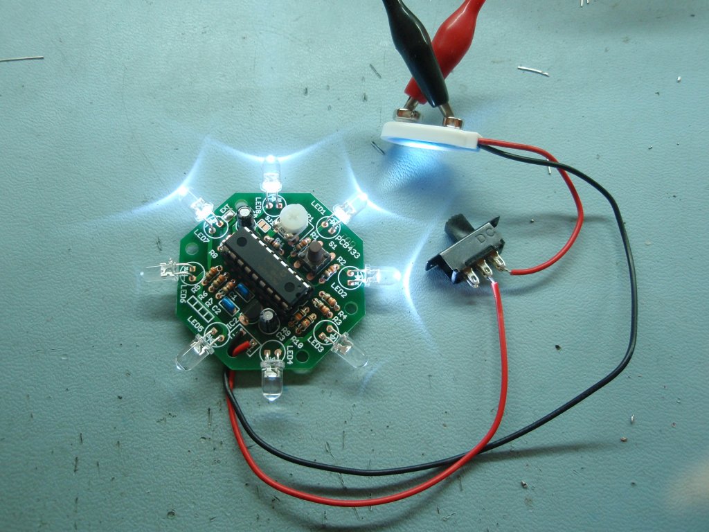
With all parts assembled, check the underside of the
board to make sure the solder joints are good and there
are not shorts or solder bridges. If the
inspection is okay, you can now connect the assembled
board to a battery or power supply.
The input voltage to
the board should be between 6 volts and 14 volts DC.
|
Power Supply
The board can be powered from a
9 volt battery such as a PP3, or a 12 volt battery including
connection to a car electrical system. Alternatively it
can be connected to a suitable DC power supply rated between 6
and 14 volts and able to supply at least 150mA.
In the UK you can buy a suitable power
adapter from Rapid Electronics. You'll also find similar
power adapters available from retail stores and e-Bay.
Rapid
Electronics 5W SWITCH MODE PLUGTOP PSU 9V 550MA
RC Part # 85-2926
If wiring to an alternative
power source (not using the battery terminal clip supplied in
the kit) make sure the polarity of the power supply is correct;
at the PCB the positive supply to the '+' and negative to the
'-' connection points.
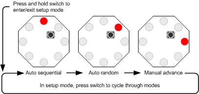
User Operation Guide
The chaser has three modes of
operation.
- Manual mode will run the
same sequence continually. When the switch is pressed it
will skip to the next sequence in program memory.
- In auto-sequential mode,
the program runs through each sequence in program memory
until it reaches the end of all defined sequences at which
point it restarts from the first one.
- In random mode the program
selects sequences randomly.
When the chaser is running in any
mode, a short press of the switch will make the controller skip
to the next sequence.
To enter setup mode, press and
hold the switch. Once it enters setup mode one of three
LEDs will light indicating the current run mode. A short
press of the switch cycles through the three modes. When the
desired run mode has been selected, press and hold the switch to
exit setup and return to run mode.
The current mode and selected
sequence are automatically saved to the PICs internal
non-volatile EEPROM memory 10 seconds after the last switch
press. When the LED chaser is next powered up it will load
and start running using the saved mode and sequence.
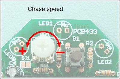
Adjusting the chase speed.
The chaser speed can be
adjusted by rotating PR1 as shown
+ increase the speed
- decrease the speed
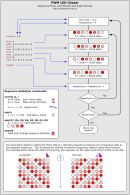
Description of Sequence Data
| The data
used to create the sequences is held in a separate
include file. You can add, remove or edit this
data to create your own chaser sequences.
To make the creation of
the data file easier a set of macros have been defined
which are used to create the sequence data. This
is described in the
Sequence data flowchart
(also available
as a JPEG image right)
If you download the
source code and look at the file named
pro433_SeqDataUFO.inc you can see the data used in this
project. You might want to edit this file as a
starting point to create some sequences of your own.
Notes:
- In manual mode,
when the repeat count reaches zero it restarts
the same sequence, to advance to the next sequence
press the switch.
- In Random mode it
will select a random sequence number to run. If
the Mirror flag is true for that sequence it will
also randomly choose to mirror the data or not.
- In auto-sequential
mode if the Mirror flag is true it will run the
sequence and then repeat it with the data mirrored.
|
 |
Firmware
The PIC supplied in the kit is
pre-programmed with the firmware
below so you don't need to do anything if you bought the kit.
Should you need to reprogram the
supplied PIC with the original code supplied, use the HEX file below.
The HEX file is ready to
program straight into the PIC chip.
The Source code will allow you
to create your own sequences and then reassemble the code to use
them with the Round PWM LED Chaser kit #433K.
Quick guide to
reassembling firmware using MPLAB
If you need a PIC Programmer I
strongly recommend the
Microchip PICKit 2,
this is available from suppliers world wide or direct from
Microchip. It's reasonably cheap to buy and reliable.
Not got a programmer? Buy
a pre-programmed PIC from the On-line store
|
Description |
Filename |
Download link |
| |
|
|
| Source
code for 16F628A |
pro481v301ufo.zip
21/02/2021 |
 download
 |
HEX file
ready to program into the PIC.
Use with 16F628A only |
pro481v301ufo.HEX
V3.0.1 21/02/2021 |
download
|
|
This firmware uses the same pro481 v3.0.1 PWM LED Chaser
'engine' code as the 481/483
PWM LED Chaser projects. The HEX file here has been assembled using
different chase sequence data that contains alternative
sequences to suit the circular LED layout of this
project. |
FAQ
Can you or
how can I make it it run
more than 8 LEDs?
This is probably the most
frequent of the frequently asked questions :-)
The project is an 8 LED Chaser
and the firmware was written to work as an 8 LED chaser.
There is no quick and easy
change to make it a 9, 12 or some other number of LED chaser.
If you need a chaser with more LEDs then this project is not
suitable for your needs.
I want to
put more than one LED on each output channel, how can I do this?
Check out the
Power MOSFET PWM LED Chaser projects
(483)
Will it work
with 3mm LEDs?
Yes, 3mm LEDs will work as will
8mm and 10mm LEDs. 3mm LEDs can be mounted on the PCB, 8mm
and 10mm LEDs would need to be connected by flying leads.
Can I use
less than 8 LEDs?
Yes, since the sequences are
user definable you can create sequences that use less than 8
LEDs.
I only want
it to run one sequence, can it do that?
Since the current mode and
selected sequence are saved to NVRAM, it always powers up in the
last mode and running the last sequence. Therefore if you
select manual mode and the sequence required, it will run only
that sequence until you change it.
Do the LEDs
have to be the same colour?
No they don't. If you
want you can mix different coloured LEDs. You can also mix
3mm/5mm/8mm/10mm LEDs if you want too.
Can it run
from a 12volt car battery?
Yes, should work fine from a
car battery. We suggest you include an in-line fuse of
250mA in series with the power lead to the board.
Can you
modify the code to run on a PIC type xyz?
The code has been written to
run on three of the most popular PICs available. If you
want to modify the source code it could be made to run on other
PIC types, however we won't modify the code.
|