This project functions as a
simple strobe for driving an LED. The use of an output
transistor allows it to pulse the strobe LED with a current up
to 100mA.
Four jumpers provide options
for changing the pulse width, strobe repeat interval and single or double
strobe flash. The programmer ready code has default
timings which are easily customised by editing values in the
PIC's EEPROM at programming time.
This is one of those
applications where it's arguably better than a 555 timer based
solution but in practice you could build it with a 555 timer
faster than you can write the PIC code. However it only
needs the code writing once, I've done that and designed a small
PCB too so away you go.
Need a high power
LED strobe?
see the Power LED Strobe project
here
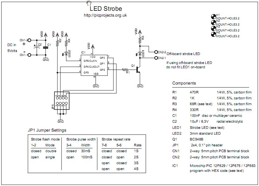
The circuit provides a LED
strobe function with jumper selectable operating modes.
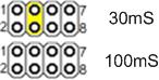
The strobe interval can be
configured using 4 jumpers for 1,2,3 or 4 seconds; strobe on time of 30mS or
100mS and single or double strobe pulse.
Since the PIC can only supply
25mA from its I/O pin a transistor is used to increase the
maximum current driven through the LED. This transistor
has a maximum collector current of 100mA which is adequate for
driving most types of 5mm LEDs. The PIC could be used to
control a higher powered output switch if desired.
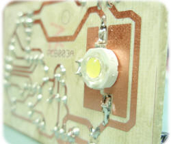
The value of R3 series current
limiting resistor for
the strobe LED has
been selected on the conservative side rather than providing maximum brightness.
With a 5 volt supply and LED with 1.8V forward voltage yields
current of approximately 47mA.
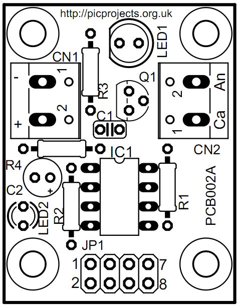
The strobe LED can either be
installed on the PCB in position LED1 or off-board via connector
CN2. If the off-board option is used do not install a LED
into position LED1 on the PCB.
LED2 is a monitor LED, if the
off-board strobe LED is used, this LED can be useful for
monitoring the operation of the circuit. If you don't want
this option, just omit LED2 and R4.
Capacitor C1 is used to
decouple the 5 volt power supply rail. If you are building the
circuit on a breadboard or stripboard you should ensure it is
located close to the PICs Vdd connection (pin 1).
The input voltage must not
exceed 5 volts. It can run from as low as 3 volts but you
will need to modify the Strobe LED resistor value. Also be
aware of the LED forward voltage; some high brightness LEDs and
in particular white LEDs and some blue and green LEDs have forward voltages in excess of 3
volts.
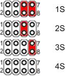
The operating modes are
selected by using jumper block JP1. If you are building
the strobe for a specific application you may want to hardwire
inputs to ground as required rather than fit the jumper pin
header.
Obviously we want the strobe
LED to be as bright as possible. It is important that the
series resistor R3 is chosen so that the LED current does not
exceed the manufacturers rating. Since different LEDs have
different maximum forward current and voltage ratings you must
select this resistor to suit the specific LED you are using.
For other LEDs you can use this
site to calculate the resistor needed
http://led.linear1.org/1led.wiz When you go to this
site it asks for the source voltage. This will be 5 volts,
or if you've used batteries to power the strobe, the total
battery voltage. Also note that driver transistor
Q1 is only rated to 100mA so do not exceed this even if the LEDs
used can.
The section refers to the
default timings used in the programmer ready firmware download.
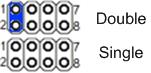
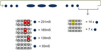
The pulse width, interval and
strobe mode are user selectable using the JP1 jumper block.
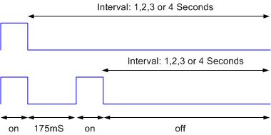
There are two strobe modes, single and double pulse. The
double mode has a (default) 175mS off-time between the two pulses.
As shown in the diagram below, the interval is measured from the
end of one pulse group to the start of the next group.
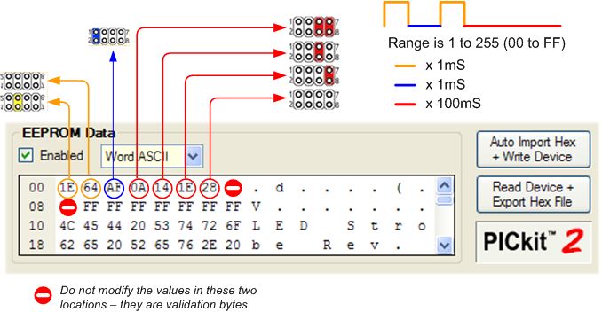
The timers for the pulse width,
interval and double mode gap are all configurable by editing the
values in the PICs EEPROM before writing the HEX into the PIC.
This is nice and easy to do and doesn't require reassembling the
code or anything complicated. Just load the HEX file from
the firmware download section into your programmer application.
Edit the values in the EEPROM as shown below and then write the
code and EEPROM data into the PIC.
Suppose you want a pulse width
of 40mS (40 x 1mS) and an interval of 1.3 Seconds (13 x 100mS) you would
set
the data in address 00 to 28 (40 decimal == 28
hexadecimal). For the 1.3 second interval change the data
in address 03 to 0D (13 decimal == 0D hexadecimal).
Values shown in the example
above are the default values in the firmware download. If
you don't modify them it will uses these timings.
Converting decimal values to
hexadecimal Depending on your programmer
the values you need to enter will probably be in hexadecimal, easiest way to
convert decimal values to hexadecimal is Google, see example
below. The prefix 0x in the result simply tells us the
value is in hexadecimal (hex for short).
You can buy all the parts
needed to build this project from most component suppliers world
wide. In the UK you can get everything from Rapid Online and
I've included a parts list with their part numbers below.
All
Rapid parts/descriptions correct at 30 January 2009. You should
check part# and descriptions are correct when ordering in case
I've made a mistake transferring them onto this page.
Component
Description
Part #
R1
PK 100 470R 0.25W CF
RESISTOR (RC)
62-0362
R2
PACK 100 1K 0.25W CF
RESISTOR (RC)
62-0370
R3*
PACK 100 39R 0.25W CF
RESISTOR (RC)
62-0336
R4**
PK 100 330R 0.25W CF
RESISTOR (RC)
62-0358
C1
100N 5MM PITCH CERAMIC
DISC CAPACITOR RC
08-0235
C2
5M MICROMIN 10UF 16V
ELECTROLYTIC (RC)
11-1506
Q1
BC548B TRANSISTOR TO92
30V NPN (RC)
81-0066
IC1***
PIC12F675-I/P (RC)
73-3284
LED1
LED 5MM HB WHITE
30000MCD (RC)
55-2484
LED2**
L-7104GD MINIATURE 3MM
GREEN LED (RC)
55-0105
socket for IC1
8 PIN 0.3IN DIL SKT
(RC)
22-0150
JP1
4+4 WAY DOUBLE ROW
HEADER PLUG RC
22-0555
CN1, CN2
2 WAY 16A
PCB TERMINAL BLOCK (RC)
21-0112
order 4
****
OPEN BLUE 2.54MM
JUMPER LINK (RC)
22-3555
Parts List Notes
All the resistors are
supplied in packs of 100
* R3 has been selected for
use with the High Brightness white LED used for LED1. On
the schematic it is shown as 68R, but 39R has been chosen for
use with this specific LED. If you use a different LED see
notes here
**
Omit R4 / LED2 if you don't need the monitor LED.
***
12F629 can also be used
****
Old PC motherboards, hard
drives etc. often use this type of jumper so you may be able
to salvage some from one of these instead of buying them.
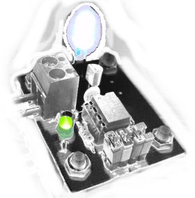
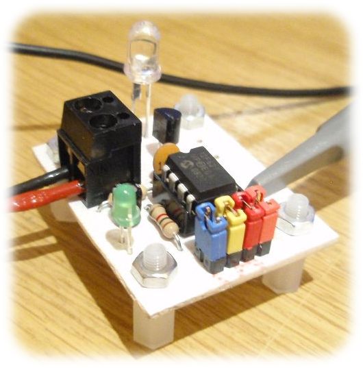
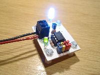
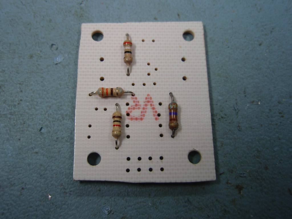
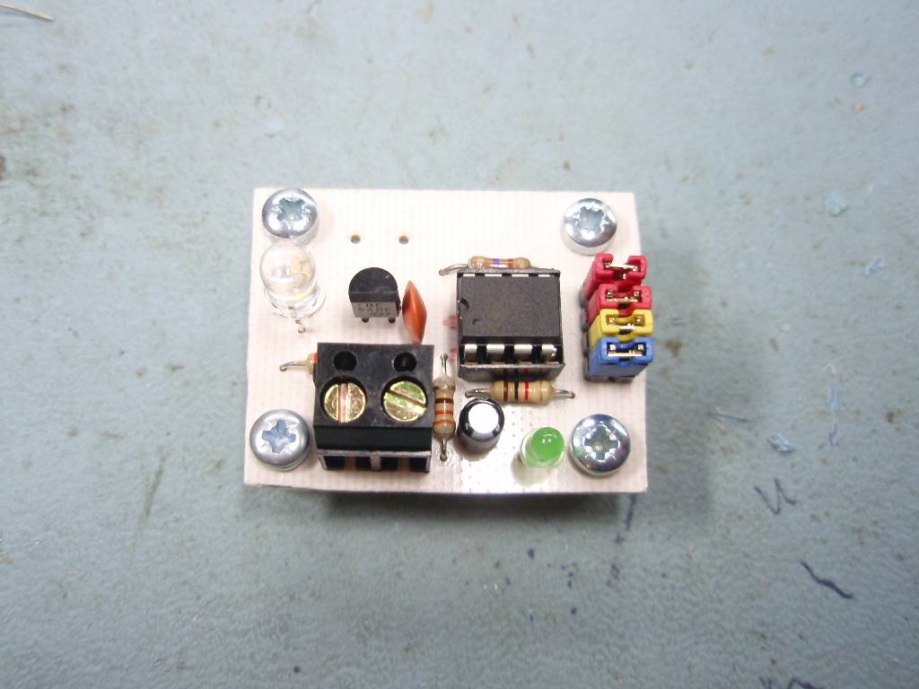
Construction is very
straightforward. Because the strobe LED has been installed
on the PCB, the connector for use with an external LED has not
been fitted in these photos.
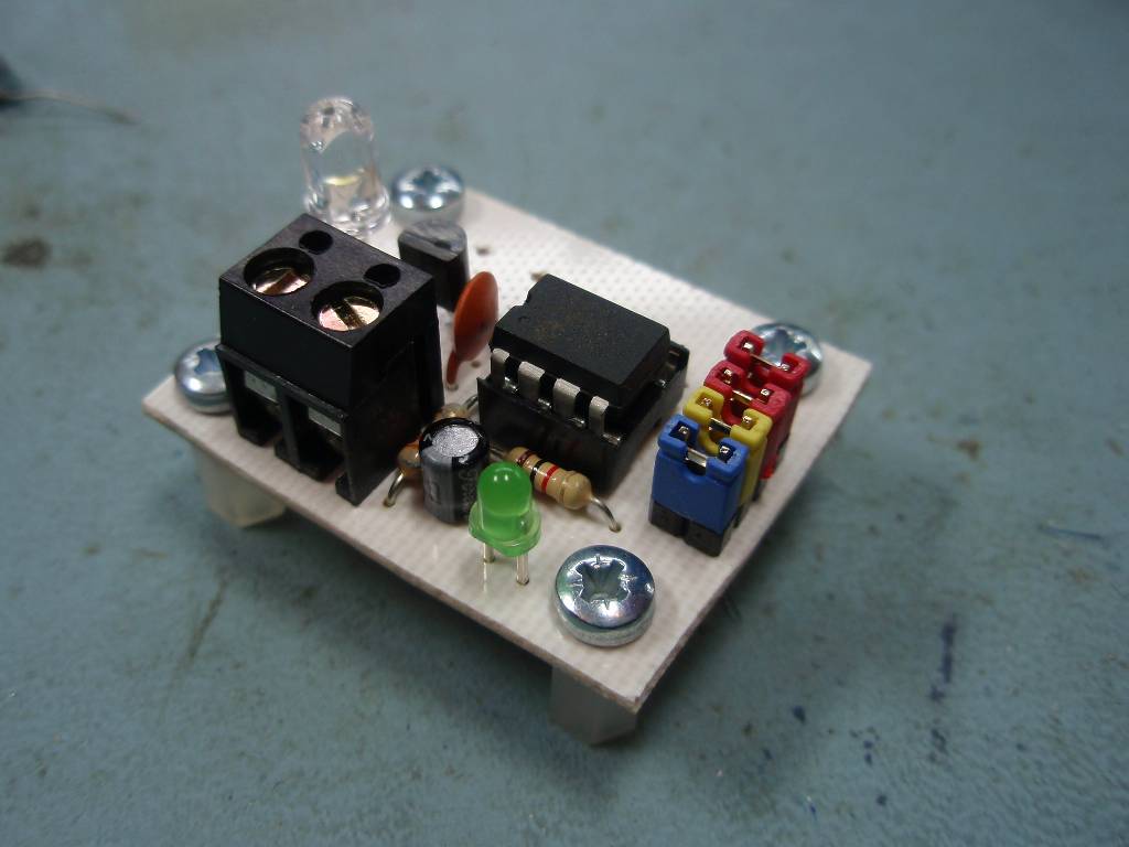
The green monitor LED is
optional; if you fit the strobe LED on the PCB you may want to
omit it.
Fig.1
Fig .2
Fig. 3
Power Supply
The LED Strobe circuit ideally
needs a 5 volt
supply. You could use 3 x 1.5V AA Alkaline batteries or 4 x
1.2V AA NiMH rechargeable batteries for portability. As noted
elsewhere on this page, it can operate at voltages down to 3
volts but the strobe LED series current limiting resistor will
need recalculating. Also some white LEDs cannot operate
from 3 volts, if they do light they are probably not operating
at maximum brightness.
The PIC itself only uses about
2mA when the strobe LED is off, the main current consumption is
when the LED is pulsed on and this will be dependant on the LED
and current limit resistor used.
You can use either a PIC 12F629
or 12F675 microcontroller with this circuit. The same
firmware code is used with either device. Download
the files required below.
The HEX file is ready to
program straight into the PIC. The asm file is the
source code which you can modify or just view to see how it
works.
Not got a programmer? Buy
a pre-programmed PIC from the
On-line store
If you need a PIC Programmer I
strongly recommend the
Microchip PICKit 2,
this is available from suppliers world wide or direct from
Microchip. It's reasonably cheap to buy and reliable.
If the LED outputs blink 3 or 4
times at regular intervals and the jumper settings are
ineffective this indicates one of two fault conditions.
The EEPROM data at addresses 07
and 08 must be 0xA9 and 0x56 respectively. If this is not
correct the 3 blink error code will be shown. You can
correct the error by reprogramming the EEPROM ensuring these
validation bytes are correct.
If the OSCCAL calibration word is
missing the 4 blink error code will be shown. You will
need to recalibrate the PIC using a PICkit2 programmer, or the
recalibration project here
This is a modified version of
the Strobe that signals the Morse Code letters 'SOS'. The
dot length can be set to one of four periods and the time
between two 'SOS' sequences can also be adjusted.
The space between the
signals forming the same letter is equal to one dot.
The space between two
letters is equal to three dots.
The space between two
words is equal to seven dots
Hardware is exactly the same as
that used with the main Strobe project on this page but requires
the alternative firmware provided below.
Jumper Settings
Jumper
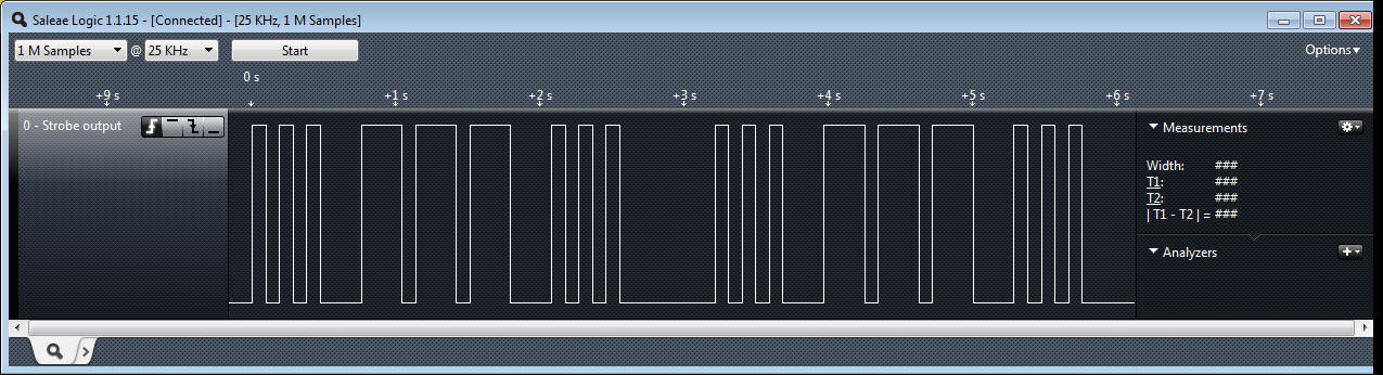
(1-2) is not used and should be left open
Strobe output
signal sampled from GPIO2 output pin (all jumpers open)
Firmware (Morse SOS version)
The hex file is ready to
program directly into a PIC12F629 or 12F675. The C source
code can also be downloaded if you want to customise timings.
It will compile with the free
MikroC compiler