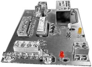
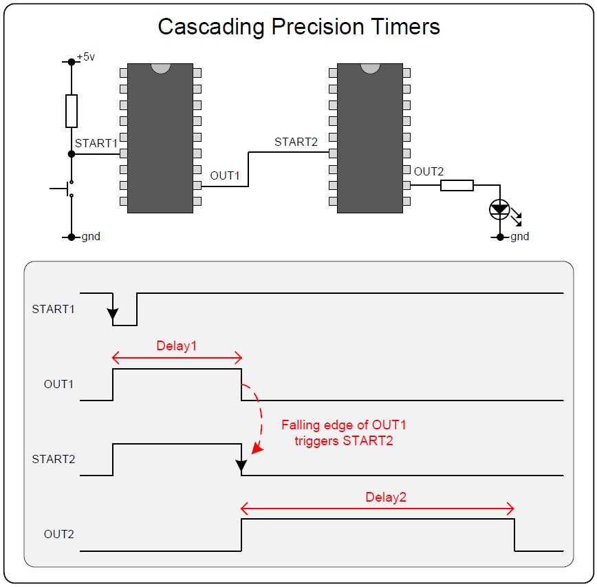
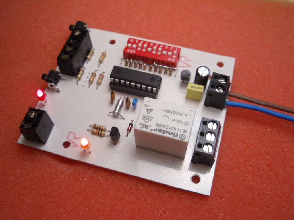
The design is presented here
as an evaluation circuit. While fully functional, the
circuit can be adapted for other applications. For
example, the output relay can be omitted and the logic signal
from the PIC used to control other systems. The start and
clr switches could also be omitted and the timer triggered from
a logic signal. Also rather than using a DIP switch, if a
specific delay is required the PIC i/o pins can be hard wired.
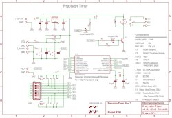
The circuit is based around
IC1, a PIC16F628A microcontroller running the precision timer
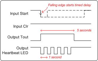
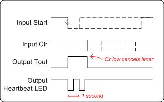
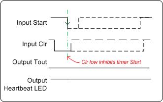
firmware. A 10 way DIP switch sets the timer delay period.
Two switches are used to start the timer and if required cancel
it during the timed period. A low-cost 32Khz watch crystal provides
an accurate oscillator clock source for the timing delays.
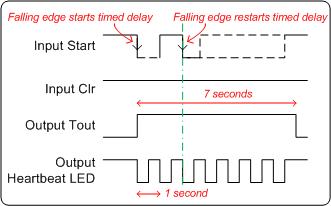
When the timer is active, the
on-board relay is turned on, a logic level output is also presented
via a terminal block connection. There are two LEDs, one providing
indication that the timer output is on, and a second blinking
'heartbeat' LED to show the timer is running.
Capacitors and Crystal
Capacitor C1 provides power
supply decoupling. It is important this is fitted as close to the power supply pins of IC1 as possible.
Ceramic capacitors come in either disc or multilayer type -
multilayer ones are generally smaller but either type will work.
Capacitors C2 and C5 provide
stabilisation of the power input to the board.
Capacitors C3 and C4 are load
capacitors for the timing crystal. Crystal XTAL1, is a
32768Hz watch crystal which provides a stable clock enabling
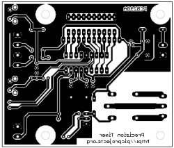
precision delays from seconds to many hours. If you don't
use the PCB for this circuit ensure that the crystal and load
capacitors are located as close to IC1 as possible. Keep
all other signals away from the crystal. (have a look
at the PCB layout note the ground plane and guard ring around
the connections between the PIC and crystal)
Capacitors C6 and C7. These are optional. If
you are using an external switch via the terminal blocks you may
need to fit these capacitors to prevent electrical noise from
the connecting wires causing a false start or clearing of the
timer.
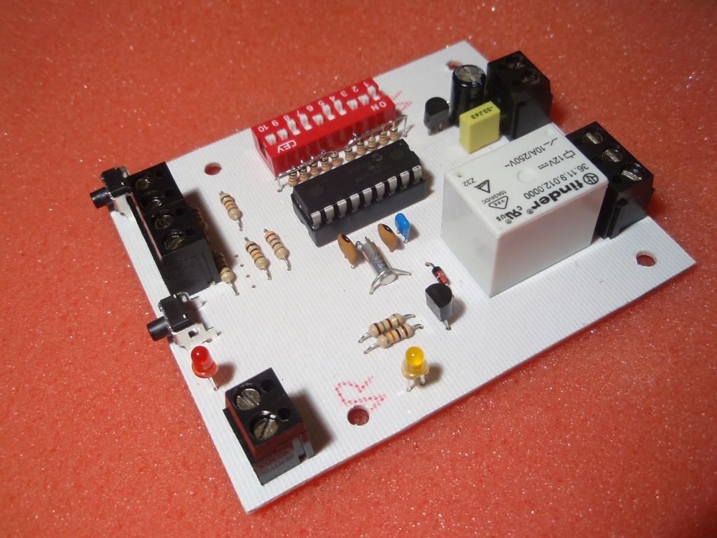
Transistor Q1 and relay
Transistor Q1 is a BC548
although any small NPN transistor will work here.
BC546/547/548/549 all work. Q1 is turned on by a high
logic output from the PIC. Resistor R1 and LED1 are
connected in series with the base of Q1, allowing the base
current to also turn the LED on. Resistor R2 ensures Q1 is
turned off when the PIC output is low and LED1 is reverse
biased. The 12 volt relay requires about 30-40mA to operate.
Diode D2 prevents back EMF from disrupting the circuit when the
relay turns off - it is important to fit this with the relay.
When the timer is running the
'heartbeat' LED blinks at 1Hz. If you don't need this
feature you can omit LED2 and R7 from the circuit.
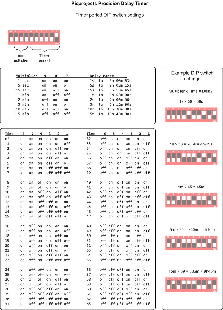
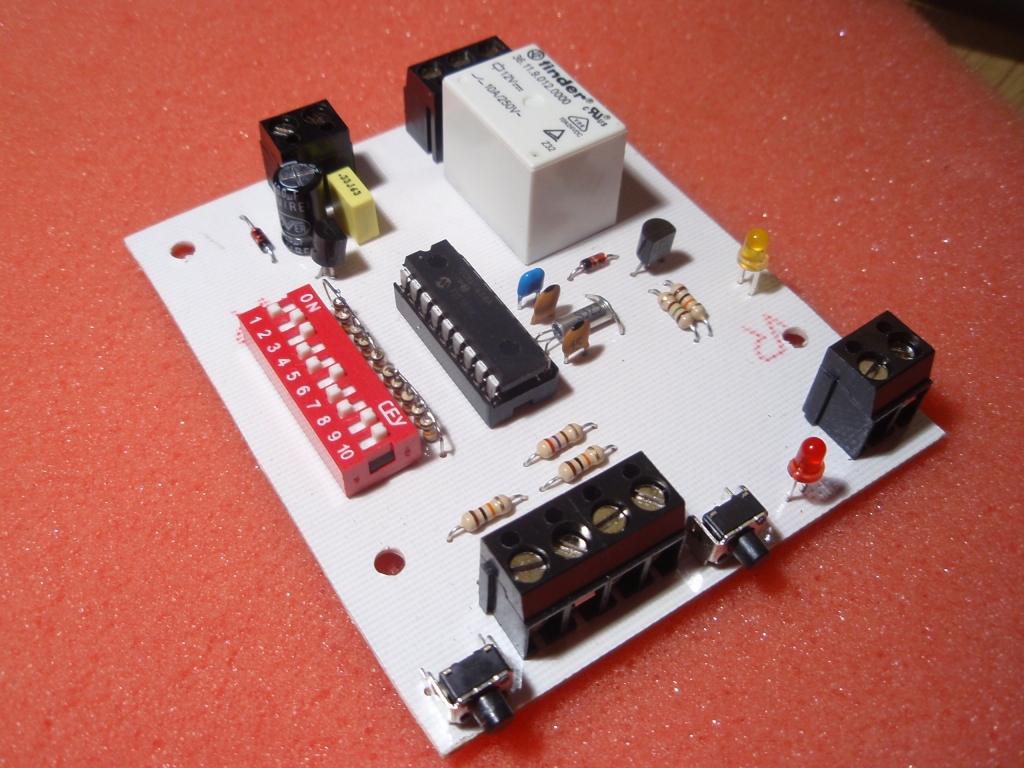
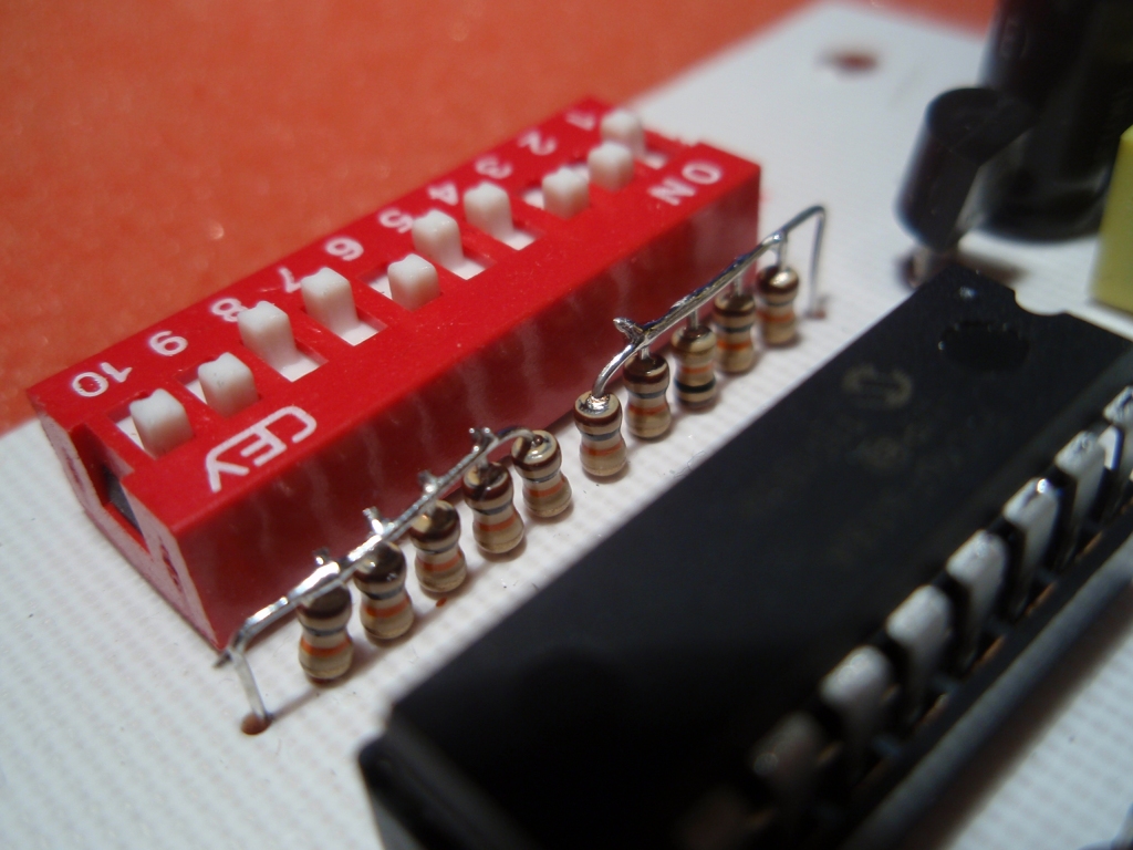
DIP Switch S3 and Resistor
networks RN1, RN2
S3 is a 10-way DIP switch.
It is used to set the delay period of the timer. The
inputs to the PIC microcontroller are pulled up by resistor
networks RN1 and RN2. When a DIP switch is set to the 'ON'
position, the corresponding PIC input is pulled low.
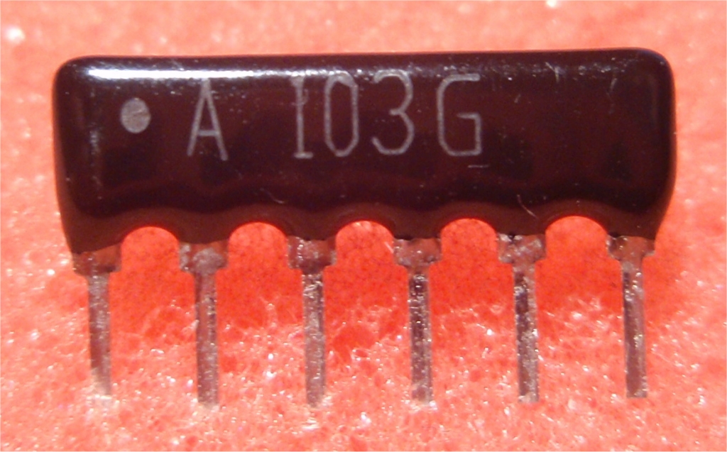
The resistor networks are
simply 5 x 10K resistors packaged together with a common
connection at one end. If you can't get hold the these you
can just use 10K resistors mounted vertically, connect the free
ends of the resistors together and then make one connection to
the +5 volt supply. (see photo right)
Power Supply
The board requires a 12 volts
DC supply to operate. The board itself can operate with a
supply from 9-18 volts DC, however with the relay fitted the
input voltage must match the coil voltage of the relay.
The incoming supply is
regulated to 5 volts by IC2, 78L05 linear regulator. D1
protects the board from reverse polarity of the input supply.
You can buy all the parts
needed to build this project from most component suppliers world
wide. In the UK you can get everything from Rapid Online and
I've included a parts list with their part numbers below.

All
Rapid parts/descriptions correct at 10 January 2013. You should
check part# and descriptions are correct when ordering in case
I've made a mistake transferring them onto this page.
|
Component |
Description |
Part # |
| R1,3,4,7 |
PACK 100 270R 0.25W CF
RESISTOR (Order 1 pack only) |
62-0356 |
| R2,5,6 |
PACK 100 10K 0.25W CF
RESISTOR (Order 1 pack only) |
62-0394 |
| RN1,RN2 |
10K 2% 5-commoned
resistor network (Order 2) |
63-0300 |
| C1 (C6,C7) |
100N 2.5MM Y5V Dielect
Ceramic Capacitor |
08-0275 |
| C2 |
100uF 25 v low imp
Electrolytic capacitor |
11-2922 |
| C3,C4 |
15pF 2.5MM NPO
Ceramic Capacitor |
08-0895 |
| C5 |
330nF 63v 5mm
Polyester Box Capacitor |
10-5830 |
| XTAL1 |
Watch Crystal
32.768KHz |
90-3052 |
| IC1* |
PIC12F628A-I/P |
73-3340 |
| IC2 |
L78L05ACZ 0.1a +5v
Voltage Regulator |
47-3278 |
| Q1 |
BC548 Transistor TO92
NPN |
81-0066 |
| D1, D2 |
1N4148 75V 200mA
signal diode |
47-5608 |
| LED1,2 |
Kingbright L934SRD-D
3mm LED Super Bright Red LED Diffused 420mcd |
55-0822 |
| socket for IC1 |
18 Pin 0.3in Turned Pin
Socket |
22-1723 |
| S1,S2 |
5.85mm Right Angle Tactile Switch 6x6mm
|
78-1154 |
| K1 |
Finder 12V Relay
(Miniature) SPDT 10A 36.11 |
60-4192 |
| Terminal block |
2 Way 16A Black
Interlocking Terminal Block (order 3) |
21-0440 |
| Terminal block |
3 Way 16A Black
Interlocking Terminal Block (Order 1) |
21-0442 |
| S3 |
DIL Switch 10-way
20-pin |
80-0344 |
Parts List Notes
All the resistors are
supplied in packs of 100
*
PIC16F628A
will need to be programmed with the HEX file available to
download at the bottom of this web page.
The firmware is for use with a
PIC16F628A microcontroller.
The HEX file is ready to
program straight into the PIC. The ZIP file contains the
source code which you can modify or just view to see how it
works.
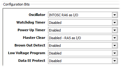
 This project uses an external
32Khz crystal for accurate timing. The crystal connects to
the same pins of the microcontroller as the ICSP programming
signals. Also the MCLR/Vpp input is configured as an I/O
input. To successfully program the hex code into the
microcontroller ensure that you:
This project uses an external
32Khz crystal for accurate timing. The crystal connects to
the same pins of the microcontroller as the ICSP programming
signals. Also the MCLR/Vpp input is configured as an I/O
input. To successfully program the hex code into the
microcontroller ensure that you:
- Program the PIC out of
circuit.
- Set the programmer
software to 'Use VPP First Program Entry' programming mode
With the PICKit2 stand-alone programmer application this
option is under the 'Tools' menu
Not got a programmer? Buy
a pre-programmed PIC from the
On-line store
Basic Version:
|
Description |
Filename |
Download link |
| Source
code for 16F628A |
ptimer.zip |
 download
 |
HEX file
ready to program into the PIC
for use with
16F628A |
ptimer.HEX V1.0.0
10/01/2013
Checksum 0x944A |
download |
PIC Configuration word settings
are already set correctly in the HEX file but should your
programmer need them they are shown below. Config Word: 0x2150
If you need a PIC Programmer I
strongly recommend the
Microchip PICKit 2,
this is available from suppliers world wide or direct from
Microchip. It's reasonably cheap to buy and reliable.