This project provides
an simple F1 motor racing style 5 light race start sequence with a
fixed or random delay that you can use on a real race track, kart circuit or
even your slot-car circuit.
Operation is simple;
when the start button is pressed all the LED clusters are off. They
then illuminate sequentially until all five LED clusters are on.
After a timed interval that can be either fixed or random depending on
requirements the LEDs extinguish, signalling the
start of the race. Once the LEDs have extinguished simply
press the start button again to initiate another race start
sequence.
The latest version of
firmware allows all the timings and the random delay to be
customised to suit individual requirements. We've also added
an output that can be used to trigger timing software or operate a
relay, sounder or other device when the start lights extinguish.
New from August 2012
is the ability to abort the start countdown sequence. This
feature has been requested by a number of people since the project
was first published.
With the new 'abort'
feature, pressing the start button again at anytime during the
countdown will immediatly set the outputs to a fixed pattern
indicating the start has been aborted. This fixed pattern
remains displayed until the start button is pressed and held for
over 1 second at which point the controller resets ready for a new
start. The feature can be disabled at the time of
purchase if it is not required.
This page presents a
complete application using 52mm (2" inch) diameter LED clusters, but the software in
the PIC microcontroller has been written to allow it to operate
electro-mechanical relays, large arrays of LEDs, low voltage lamps,
or even simply small 3/5/8 or 10mm LEDs.
When the circuit is first powered
on the outputs do the following.
2 seconds
Only appears if Start switch
input is active (switch pressed) LED's will stay in
this state until Start switch is released.
8 seconds (or Start switch
pressed)
Start sequence
When the start switch is pressed
and released the first output turns on followed by the next four
outputs. Default timings set the interval between each LED turning
on at 1 second but this can be customised.
After the fifth output has been on
for 1 second, the controller starts a random delay that will last
anywhere from 0 to 4 seconds at which point all outputs are turned
off. Again the duration of the random delay can be changed to
suit requirements, or it can be set to a fixed period.
Once a start sequence has
completed, simply press the start button again to initiate another
start.
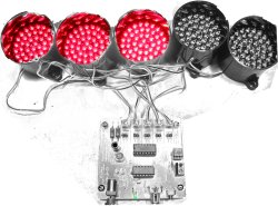
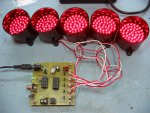
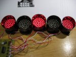
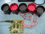
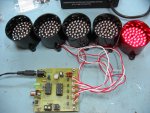
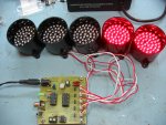
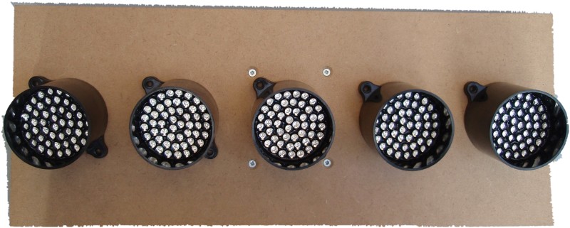
Photo showing operation with 2 rows
of 5 LED clusters (built on prototype during
development)
Update: The
preassembled board now ships with Firmware V5 which supports an 'abort start'
function.
The 'abort start'
function is very simple to operate, using the same switch used to
trigger the start countdown sequence.
After the switch has
been released to trigger the start sequence it can be pressed again
at any time during the countdown to abort the start.
If the start is
aborted a fixed pattern is immediatley displayed on the light
outputs. This can only be cleared by holding the start switch
down again for over 1 second resetting the controller ready for a
new start.
If this feature isn't
required you can request to have it disabled when ordering a kit or
programmed PIC.
Timing and mode
options are held in the PICs EEPROM. These values can be set
when the PIC is programmed. If you have access to a PICkit2
programmer the values can also be re-configured by the end user.
PICs supplied in the kit will have default timings set. If you
want customized timings you can provide us with a list of time
values for each parameter shown in the timing data and we will
pre-program them into the PIC supplied with the kit.
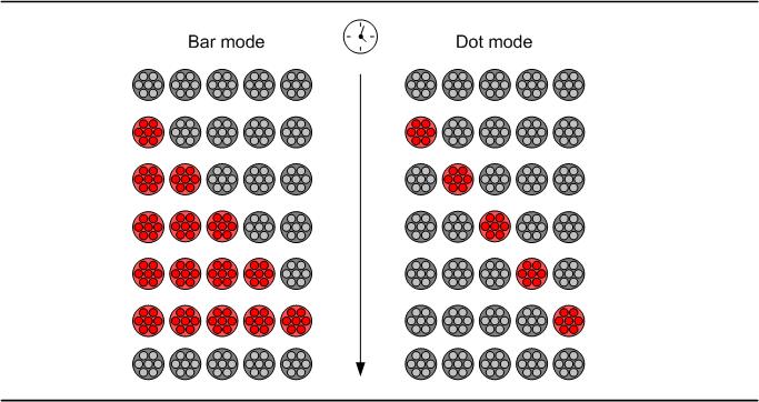
The outputs can operate in
either bar or dot mode.
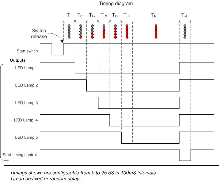
Timing Data
The timing diagram shows
all the parameters that can be configured. These can
be set from 0 to 25.5 seconds in 100mS intervals
Default timings and mode
supplied in the kit.
0
; light mode value, 00 bar, >00 dot
0 ; pre-light hold time value x 100mS [TP]
10 ; light 1 on time value x 100mS [TL1]
10 ; light 2 on time value x 100mS [TL2]
10 ; light 3 on time value x 100mS [TL3]
10 ; light 4 on time value x 100mS [TL4]
10 ; light 5 on time value x 100mS [TL5]
40 ; end hold delay value x 100mS (or maximum random time)[TH]
0 ; end mode value.
; 0 for random end delay
; >0 for
fixed end delay
5 ; start gate output time value x 100mS [TSTC]
; If TSTC= 0, start gate output is
always on except when
; start sequence is active
41 ; b'00010101' abort hold light state.
1 ; 0 - abort feature not enabled
; 1 - abort function enabled
The above timings summarised
are:
5 lights
illuminating in bar mode at 1 second intervals.
0-4
second random delay at the end.
Start gate output is
active for 0.5S
Abort function is enabled and
displays '0-0-0' pattern on light outputs
For step-by-step guide to editing and reprogramming the EEPROM
timing data see here
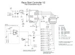
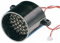
The circuit described
on this page is designed around Kingbright's 52mm LED cluster module
which comprises 50 red LEDs in a waterproof housing with a
brightness in excess of 16000mcd. In the original version of
this project each LED cluster was directly driven and all those
LED's required a hefty current with the ten LED cluster version
requiring a power supply capable of delivering over 2amps at 12V DC.
The input power to the
board can be fed from either the DC Jack or 2-way screw terminal
block. These connectors are wired in parallel to give a choice
of connection. The positive supply is
fed to the rest of the board via D1 which provides protection against a reversed power
connection to the board. D1 is a Schottky diode and is used in
preference to a standard diode because of its a low forward voltage
drop of around 0.25 volts. A 78L05 voltage regulator provides
the 5 volt supply for the PIC and a ULN2003A interfaces the PIC
outputs to the LED modules. LED1 is connected across the
output of the 78L05 to provide a power-on indication.
The start switch input
connects to the PIC via R3,R4 and C3 which provide immunity to
false triggering from electrical noise. If the start switch is
located more than a couple of metres from the control PCB it is
advisable to use the isolated switch input which offers greater
protection against both false triggering and spikes on the input.
The controller
also includes an optional isolated switch input. This uses an
CNY17 opto-coupler which provides an electrically isolated trigger
input for the controller. This allows the start to be triggered from another
device such as a computer timing system. It also provides electrical isolation for safety reasons, or
can be used to reduce the possibility of false triggering in an electrically noisy
environment. Resistor R6 provides current limiting for the LED inside
the CNY17 and D2 protects against reverse connection of the power to
the isolated input.
The LED modules are
driven by a ULN2003A darlington transistor array. The board
supports two rows of 5 LEDs with each row using a single current
limit resistor (R1/R2). The LEDs are driven with a PWM signal
to allow adjustment of the overall brightness. Since all the
LEDs in one row share a single current limit resistor, the LEDs are
driven one at a time. This means only one LED
module is ever actually on but the output scans at ~350Hz so they
appear to be on simultaneously. As mentioned above, this reduces the current requirements from
just over 2amps for a 10 LED setup to
under 500mA. If only a single row of LED modules are used this
drops to around 260mA.
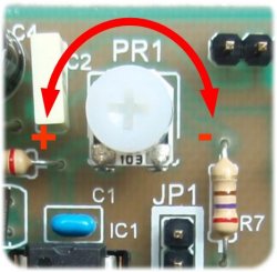
The brightness of the
LED modules can be adjusted using potentiometer PR1. This
feeds a voltage between 0 and 5 volts to the PICs internal analogue
to digital converter. The digitised value is then used to adjust the
duty cycle of the PWM output to the LED modules.
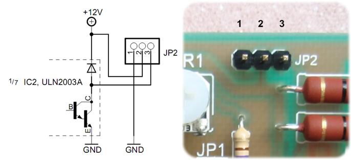
JP2 provides a timing
start gate output for external equipment. This is an
open-collector output that is driven low for a fixed duration at the
completion of the LED start sequence. This can be used to
trigger an external timing system, release a start gate, or drive
another LED cluster. Additional circuitry may be required
depending on the specific application. Since it's primarily
intended to trigger another device or system at the end of the
timing sequence this output is not driven with a PWM signal.
If it's used to drive a LED module, the brightness isn't adjustable
using PR1.
Power can be supplied
to the board either through the DC Jack connector or the 2-way screw
terminal block. These connectors are wired in parallel so if
the DC Jack is used for the power input, the 2-way screw terminal
connector can be used as an auxiliary DC output if required.
The board requires a 12 volt DC supply rated for a minimum of 300mA for a single
row of LED clusters or 600mA for a dual row. A 13.8 volt
supply can also be used (see here)
LED Clusters
The board supports
either a single row of LED cluster modules or two rows. For
use with a single row connect the five LED cluster modules to column
A header pins. For a two row LED cluster setup connect the first
row to Column A header pins and the second row to Column B header
pins.
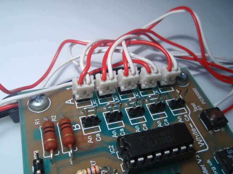
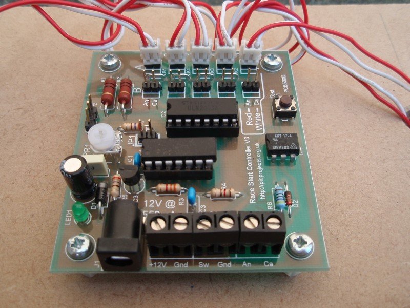
The connector from LED
cluster modules has a red and white wire attached. The Red
wire should be connected to the An pin of the 2-pin header, the
white wire to the Ca pin as indicated by the PCB overlay text.
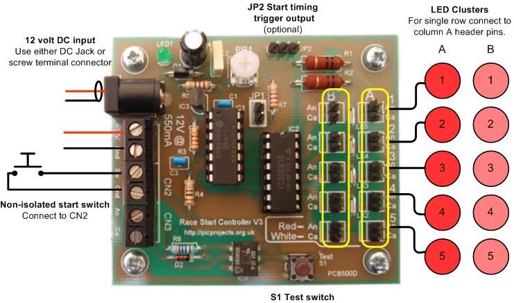
There are a several options for
connecting the start switch to the board. There is a direct
connection input and also an opto-isolated
input. The isolated input can be
used where the switch is a long way from the board, or in
electrically noisy environments. It can also be used to
trigger a start sequence from a computer or other equipment.
Input option 1.
If the start switch will be located within a couple of metres of the
board, use the non-isolated switch option. The switch is
connected directly to the CN2 input of the board.
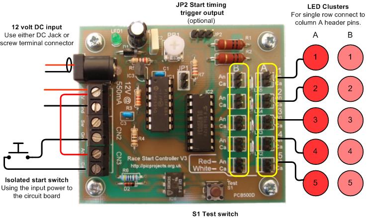
Input option 2
Use input option 2 if the switch
will be located more than a couple of metres from the board, or in
an electrically noisy environment. With this option the power
for the isolated input comes from the input power to the board.
The opto-isolator prevents noise and spikes from false triggering or
damaging the microcontroller. This option doesn't require a
second power source for the isolated input since it shares the input
power to the board.
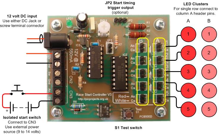
Input option 3 Use input option 3 if you need to
trigger the start sequence from other equipment such as a computer
or you need to keep the controller electrically isolated.
This option keeps the electrical power for the two systems
completely isolated.
S1 Test switch
The S1 test switch fitted to the
PCB can be used to trigger a start sequence with or without an
external switch / isolated switch connected to the board.
Useful for testing the board at assembly time and troubleshooting
during normal use.
For more detailed information see
the 'Operating notes' section
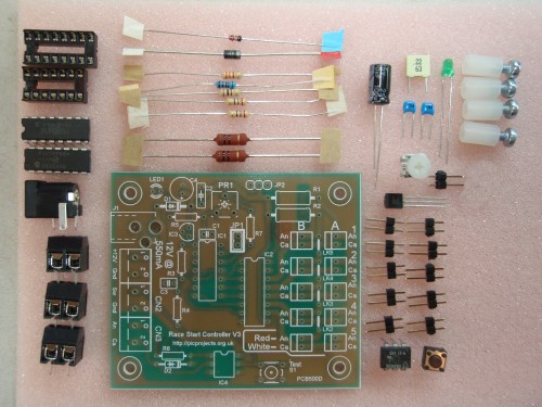
Parts List
A complete kit of
parts, including the PCB can be bought from the
Picprojects on-line shop. The kit includes the parts
listed. It does not include the LED cluster modules or power
supply.
The LED Cluster, power supply and a
suitable start button switch can all be sourced from Rapid Electronics
and delivery is free on orders over £30. The part numbers to order
are shown below.
Description
Part #
Qty
52MM ULTRABRIGHT LED CLUSTER
(RC)
56-2985
5 (10)
LRG RED PUSH TO MAKE SWITCH
(RC)
78-1550
1
15W MINIPLUG TOP PSU 12V
DC1.2AMP (RC)
85-2902
1
The Kingbright LED
clusters are also available from a other UK Suppliers
Construction details
for the PCB version are presented in pictures below. The
assembly is fairly straightforward however a few components do need
to be installed the correct way round. Read through the whole
of this section before starting assembly, then refer to it during
assembly.
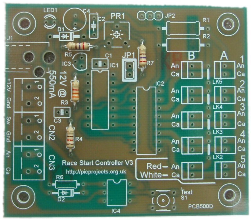
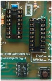
Unpopulated PCB. The
white markings are the component overlay. This shows
where to fit the components and in some cases which way
round to fit them. Follow it carefully.
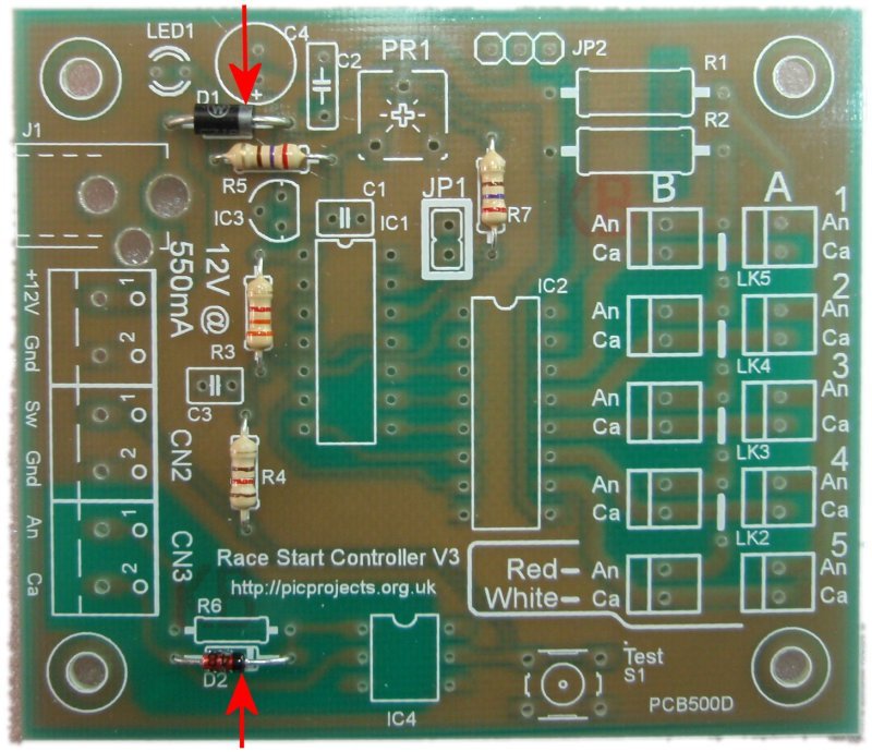
Diodes D1 and D2 must be
fitted the correct way round. Each diode has a band
around one end. They should be installed with the band
matching the component overlay as shown
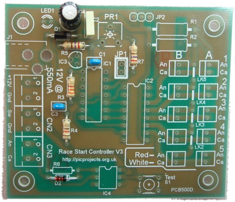
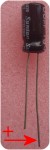
Now install the capacitors.
C4 must be installed the correct way round. One lead
is longer than the other; this is the positive lead.
On the PCB overlay you will see a small '+' symbol next to
one hole. The long lead should be fitted through this
hole, the short lead through the other.
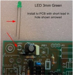
Install LED1 with the
short lead nearest the corner of the board as shown in the photo.
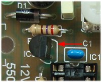
Install the 78L05 voltage
regulator with the flat face matching the component overlay
as shown. You will need to bend the centre lead back
slightly to fit the holes in the PCB.
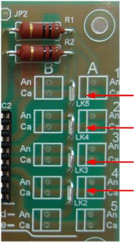
Fit resistor R1 and R2.
Once they are soldered in place carefully trim the wire
leads.
These wires should be used to make the four wire links LK2, LK3, LK4 and
LK4 (photo right) (n.b. you can actually use any of the component lead
off-cuts for these links)
There are two IC sockets which
should be installed into positions IC1 and IC2. These have a
small notch in one end, align the notch with the marking on
the overlay.
Install PR1, S1, and IC3.
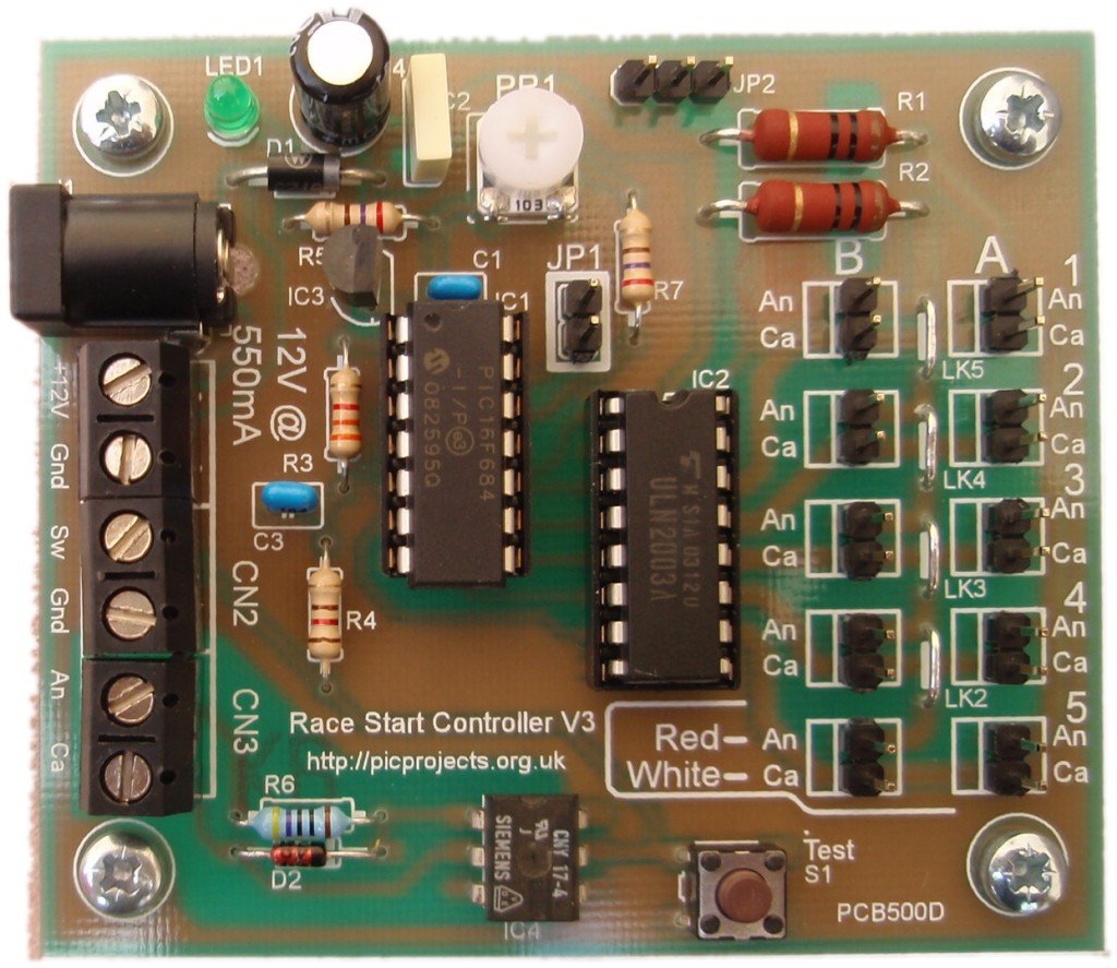
The board should now look like the one above.
When installing IC's 1,2 and 3
make sure they are fitted the correct way round. The
body of the chip has a notch in one end (arrowed above).
The chips must be fitted with the notch as shown. Also check
the pins don't get bent under the device instead of going
into the hole/socket.
Finish off by installing the
2-pin headers, screw terminal blocks and the DC Power
Socket. Fit the nylon PCB spacers using the M3 screws.
The board should now look similar to the one above
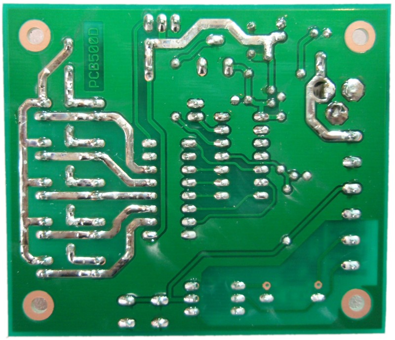
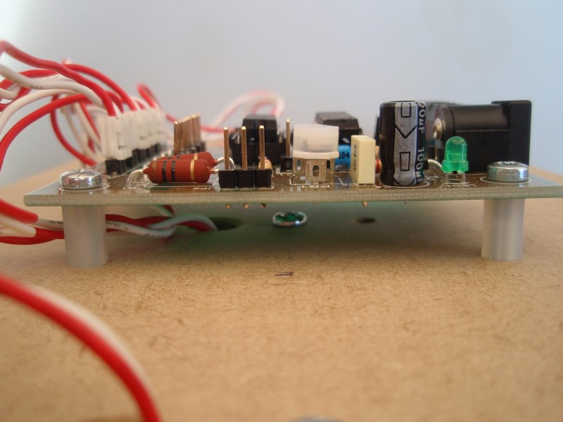
On the underside of the board
there are some exposed copper tracks. These should be
tinned with solder as the photo shows. While you're
doing this inspect the board for poor solder joints, solder
splashes etc. and correct them.
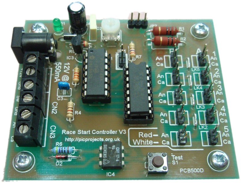
Completed board
If you have a multimeter to
hand, we suggest you remove IC1 from its socket.
Apply 12 volts to the input power connector. If LED1
lights, measure the voltage between pins 1 and 14 of the IC1
socket. This should measure 5 volts +/- 0.25 volt.
The board needs a
DC regulated input of 12 volts. This should be rated for at least 300mA for a single row of LED
clusters or 600mA for a dual row. The circuit will only
draw the current it needs so if you have a power supply rated
for higher current, as long as its output is 12 volts, this will
be ideal.
If you wish to use
a 13.8 volt power supply replace D1 (1N5417) with two 1N4001
diodes in series. (If you're buying the kit and you
intend to use a 13.8 volt supply, let us know when you place the
order and we'll supply a pair of 1N4001 instead of the 1N5417)
Do not use an unregulated DC power supply as these generally
only deliver the specified voltage at full load.
As the
board has no fuse or over current protection, this should be
provided externally. Typically a regulated DC power supply
will have overload protection built-in and if this is the case
nothing further is required. If you power the circuit from
a battery or other source then you must ensure there is a
suitable in-line fuse.
The DC Jack and
2-pin screw terminal block are connected in parallel. Either
connector can be used. If power is applied through the DC
Jack, the screw terminal block can be used as an auxiliary power
output.
Switch Inputs
The start sequence
is triggered on the release (contacts opening) of the switch not
the initial press.
There are two
external inputs (CN2 / CN3) and an on-board switch S1. Any of the
these can be used to operate the unit; you choose which one
depending on your specific requirements. (see
Board Connections section
above)
The onboard switch
and the two inputs are
connected to the controller in a wired 'OR' configuration.
This means any
or all switch/inputs can be used at the same time and the use of
one does not preclude the use of the others.
S1 Switch
The S1 switch on
the PCB can be used for testing the board without any external
switches connected.
Non isolated switch
input
The CN2 connector
provides input for a non-isolated switch to be connected to the
controller.
The isolated
switch input needs its own power source to turn the LED on in
the opto-isolator. The 470R resistor supplied in the
kit is suitable for voltages in the range 9-14 volts.
If you use a
voltage outside this range you will need to substitute R6 with a
different value resistor according to the voltage used in the
external circuit.
Suggested values
for R6:
3 to 5 volts
use 150R (5% 0.25 watt carbon film)
6 to 8 volts use 220R (5% 0.25 watt carbon film) 9 to 14 volts use 470R (2% 0.6 watt metal film - supplied
with kit)
15 to 18 volts use 560R (2% 0.6 watt metal film)
for safety reasons do not
use voltages > 18volts at this input
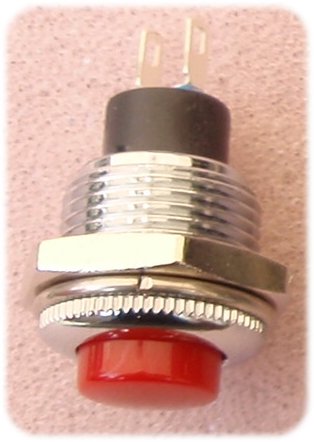
External start button
You can use
any suitable
push button switch with normally open (NO) contacts.
The start
button that can be seen in the photos on this page is
available from Rapid Electronics
part # 78-0182. (also see part # 78-1550)
The LED clusters
are
Kingbright type BL0307-50-44.
These contain 50 LED's connected as 10 parallel strings of 5
LEDs as shown in the schematic below. The
Kingbright LED clusters are available from a number of UK
Suppliers
Ensure they're connected to the
controller with the red and white leads as shown in both the
photos and indicated on the PCB overlay. The LED
clusters illuminate sequentially from 1 to 5 and the connectors
on the PCB overlay are numbered accordingly.
Adjusting
Brightness
When JP1 is open,
the controller drives the outputs using a PWM (pulse width
modulated) signal. This allows the brightness of the LEDs
to be controlled by adjusting the position of PR1. The PWM
frequency is ~350Hz to avoid any visible flickering.
The brightness
control input is an analogue signal varying from 0 volts (dim)
to 5 volts (bright). For the technically minded it is
possible to modify the circuit to use a Light Dependant Resistor
or similar device to automatically adjust the LED brightness to match the ambient
lighting.
JP2 Start Gate
Timing Trigger
JP2 connector
provides an open-collector output that can be used to
trigger a timing control system, activate a light or buzzer.
The output is active at the end of the start sequence when
the LEDs go out. The duration of the output pulse is
configurable (default 500mS)
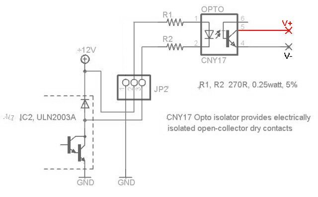
If you
need isolated dry contacts, use JP2 with an external
CNY17 opto-isolator as shown. Connect the output
of the opto-isolator (pins 5,6) to the equipment being
controlled.
Two resistors are used to keep power dissipation below
0.25W in each resistor.
The actual output transistor
is part of IC2 and it can sink up to 500mA.
Since it is part of IC2 there is an internal diode connected
to the boards 12 volt supply. This should be taken
into account when making connection to an external circuit.
In particular ensure when the output transistor is off, the
voltage at pin 3 does not exceed 12 volts otherwise the
ULN2003A's internal diode will be forward biased and damage may
occur.
The applications for the grid start
controller project are varied and you will probably want to design
your own housing for the complete assembly.
The drawing below is a suggested
layout with dimensions for the construction of a board to mount the LED cluster
modules and control PCB.
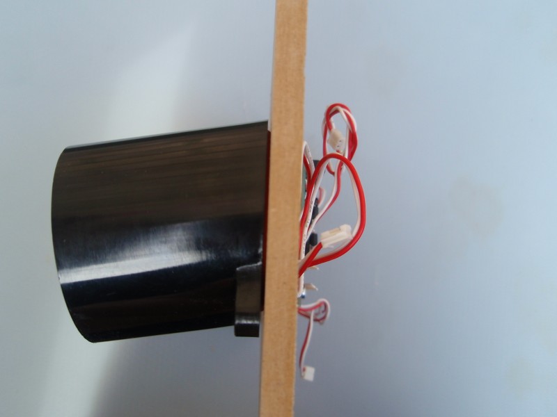
The example below is constructed on
6mm MDF. The LED Cluster modules have a neoprene sealing ring
on the back of the module so with some thought the entire assembly
could be made weather / rain proof.
For a two row board, you will
need to duplicate the holes for the LED modules above the
first row. Don't duplicate the holes for mounting the
control PCB.
Since the control PCB is
mounted directly behind the middle LED module, it should be
installed after the LED modules otherwise you can't get to
the fixing bolt.
Photos below illustrate the
assembly construction:
If you have
built the kit to work with the LED cluster modules you can skip
this section.
The information here is useful if you
plan on using the controller to operate relays or an alternative
LED driver design.
The software
supports three drive modes of which two are supported on the
PCB. The third mode may be used if you incorporate the
microcontroller into your own hardware design.
The design of the
circuit uses a single current limiting resistor (R1 & R2) for
each row of LED clusters. For this to work only one LED cluster
can be on at any time otherwise the more LEDs that turn on, the
dimmer they get. The software drives each output one at a
time but it does so 350 times a second which makes them appear
to the human eye to be on at the same time. The
reason it has been implemented this way is for two reasons.
The total
maximum current required is that of 2 LED clusters rather
than 10 so a smaller and cheaper power supply can be used.
The drive
circuit uses a single ULN2003A transistor array and two
resistors which keeps the cost down and the complexity of
the circuit and PCB layout are simplified.
The output drive
modes are jumper selectable.
Mode
RA0 (JP1)
RA4
Supported
on PCB
Direct
closed
open
Use with relays and other devices that can't use PWM
Y
Direct PWM
*
open
closed (Gnd)
Use with LED driver that has individual current
limiting
N
Multiplexed
PWM
open
open
Use with LED driver that has common current limiting
Y
The RA0 / RA4 inputs have
internal weak-pull enabled so there is no need for external pull
up resistors.
* On the PCB, RA0 is connected
to JP1 but RA4 is not made directly available since the Direct PWM mode isn't supported by the hardware on the PCB.
Driving LED clusters with
individual current limiting
The Direct PWM mode drives the
outputs with a PWM signal which allows PR1 to adjust their
brightness. In this mode all the outputs are active
simultaneously which requires individual current limiting for
each LED module and a suitable output driver device that can
handle the current/power dissipation. This mode is enabled
by connecting RA4 to ground. Since this mode isn't support
by the hardware on the PCB, there is no jumper on the PCB for
it. The functionality is provided if you want to
incorporate the PIC microcontroller into a bespoke hardware
design.
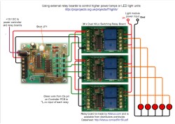
If you need to drive lights or
LED units that require more power, current or voltage than the
controller board is designed for, you can interface the
controller via relay driver boards.
A pictorial schematic for
connecting relay driver boards is shown right. Click on
the link for PDF
Ensure JP1 is closed
(either fit a jumper to the 2-pin header, or install a wire
link). If JP1 is not closed the relays will be driven with a PWM signal and won't
operate correctly.
The Relays boards are made
by Kitsrus.com
and are available from distributors worldwide
Datasheet:
http://kitsrus.com/pdf/k156.pdf Please note Picprojects is not able to supply these relay
boards
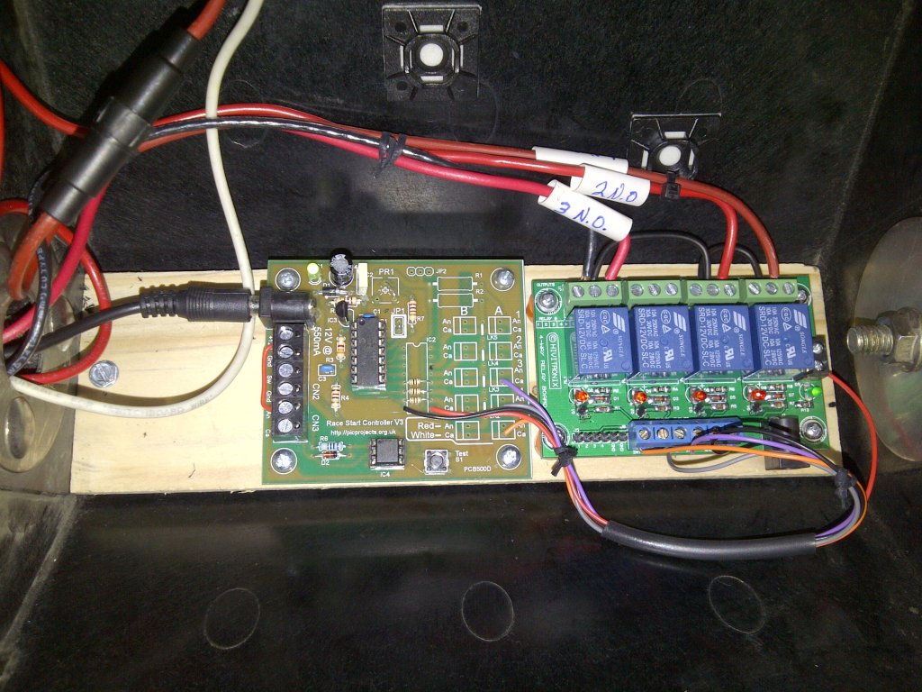
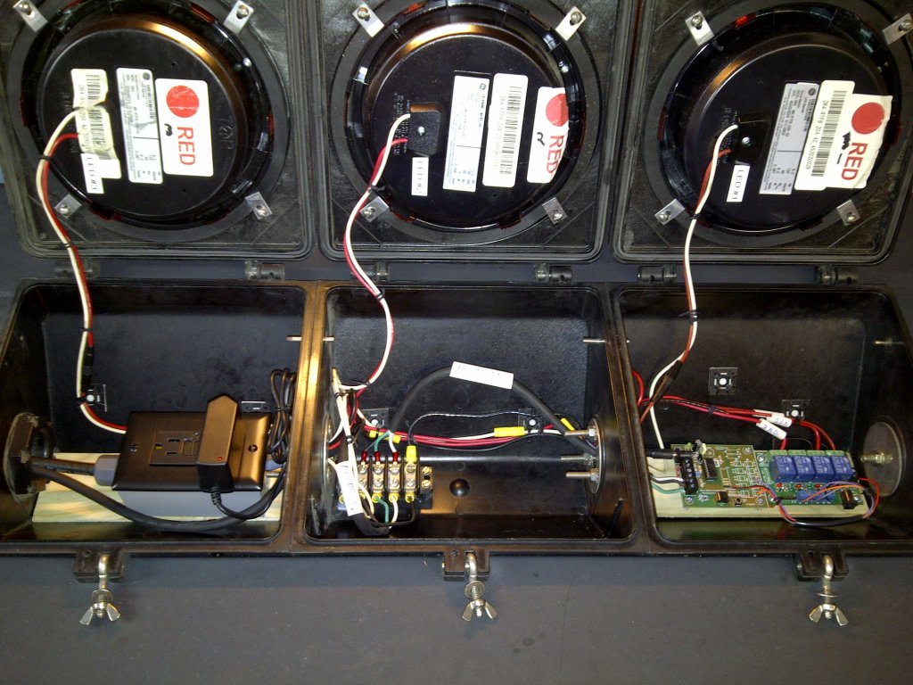
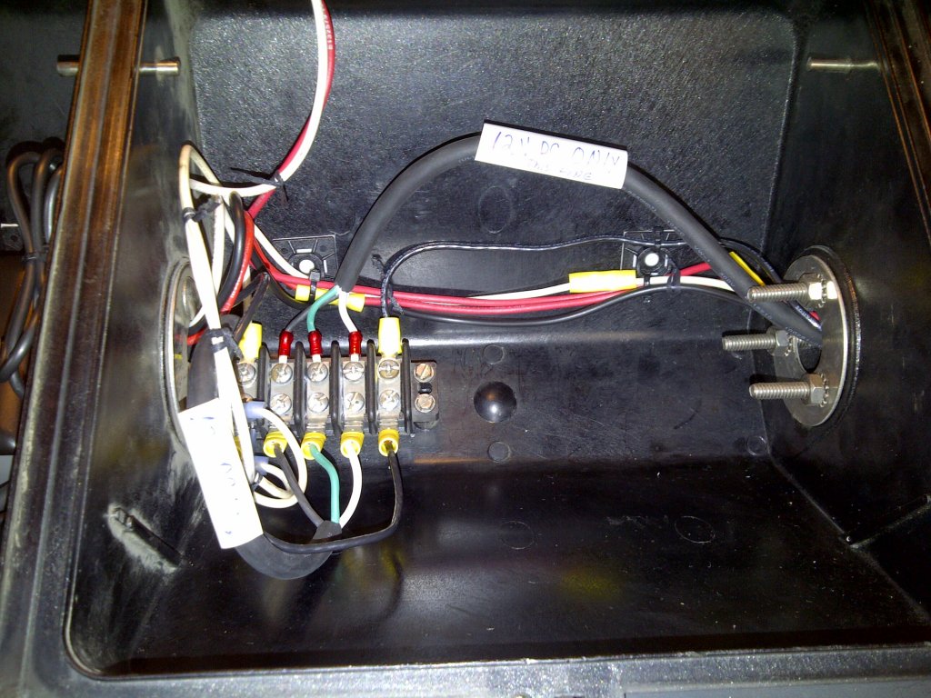
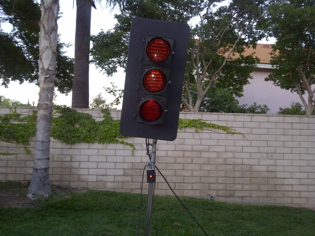
Custom control board
The photographs below are courtesy
of Chris Hutchinson - Los Angeles Karting Championship
Chris used some 120 volt LED
modules for the 'traffic light'. As this only required 3
outputs driving a relay module the control board was supplied custom
assembled without the components for the 12 volt LED modules.
Since only 3 channels were required custom timing parameters were
used. By setting the delay on the first two channels to 0 it
effectively makes it start from channel 3. The first two channels
aren't used.
Firmware and source code for
PIC16F1823 microcontroller. The original project used a
PIC16F684 but the code has been rewritten for the PIC16F1823.
This is pin compatible with the 16F684 and works directly with the
hardware for the project on this web page. (While the devices are
pin compatible the firmware is not backward compatible with the
older PIC16F684). If the HEX file opens as a text file, try right-clicking on the link and save-as