This section covers how the
circuit works, but you don't need to understand it to build a
working charger sharing controller, so feel free to skip it.
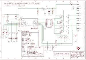
The circuit is controlled by
IC2, a PIC16F628A microcontroller running firmware written in
MikroC (firmware and compiler can be downloaded free)
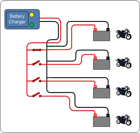
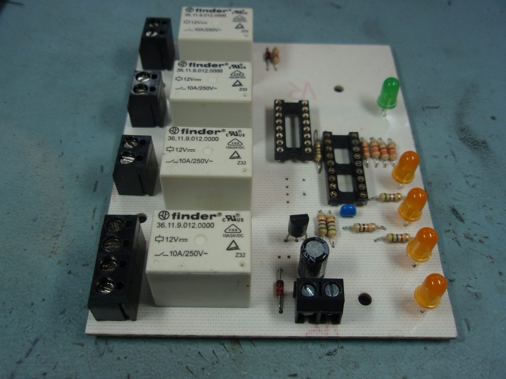
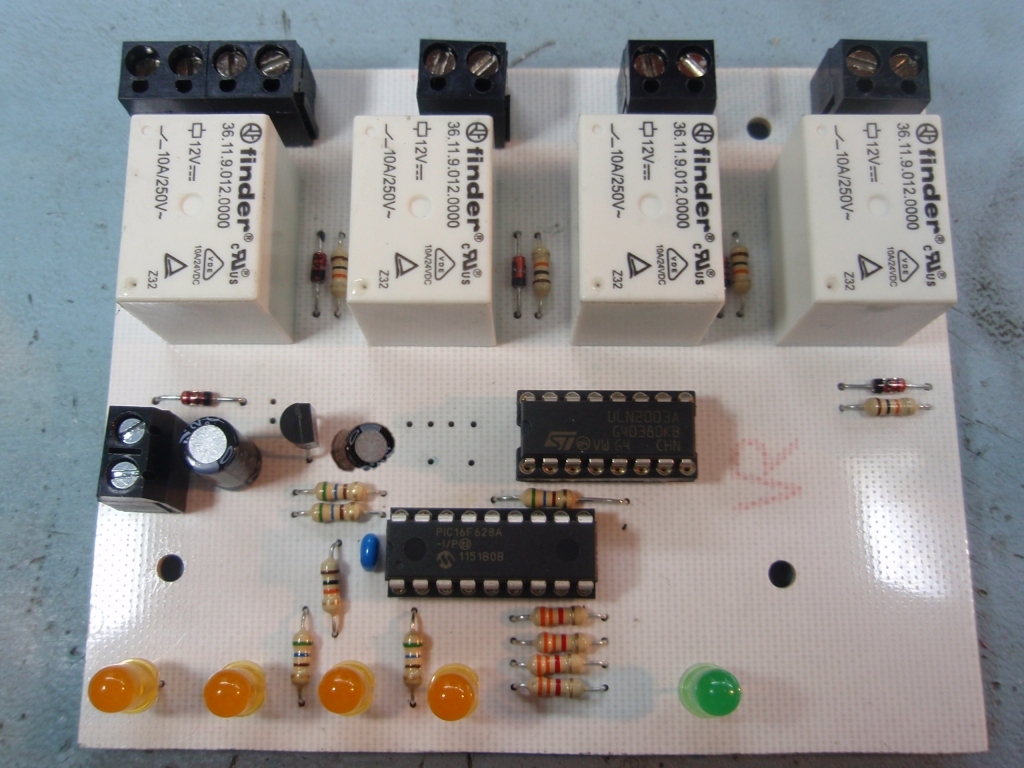
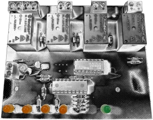
There are four single pole
relays on the PCB that connect the input from the battery
charger to each individual output. The software controls
the operation of the relays so that only one relay is active at
any time. When switching from one bike to the next all outputs are switched off for 30
seconds to allow the charger to 'see' the disconnection and
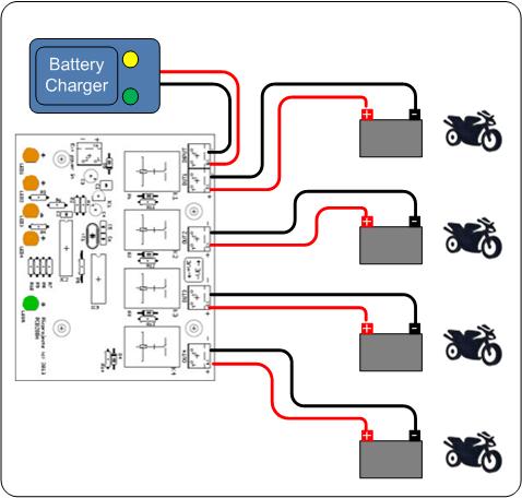
reset itself. Each output is active for
approximately 8 hours and the controller cycles round the
outputs sequentially so all four outputs will connect over a 32
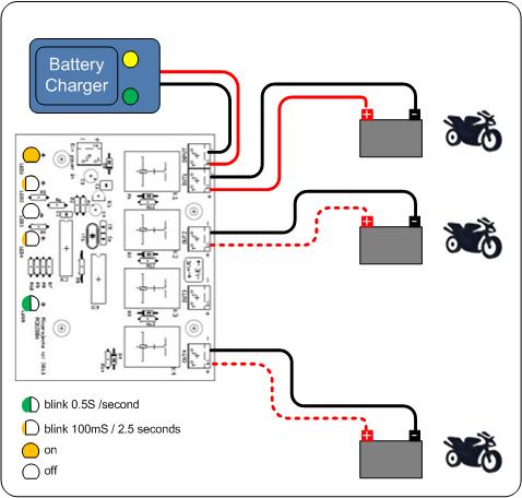
hour period. The controller senses the presence of the
bike battery on each output so unconnected outputs are skipped
e.g. if only two bikes are connected each bike gets an 8 hour
charge every 16 hours. The timings are written into the
controller software, if you want to change them you will need to
edit and recompile the C source code.
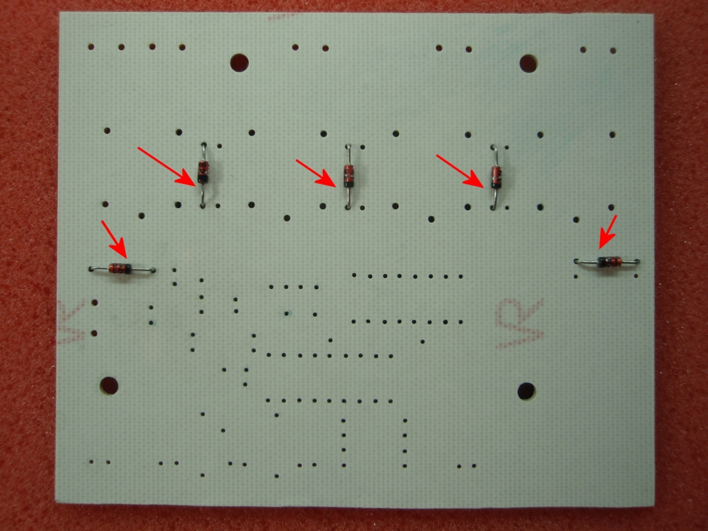
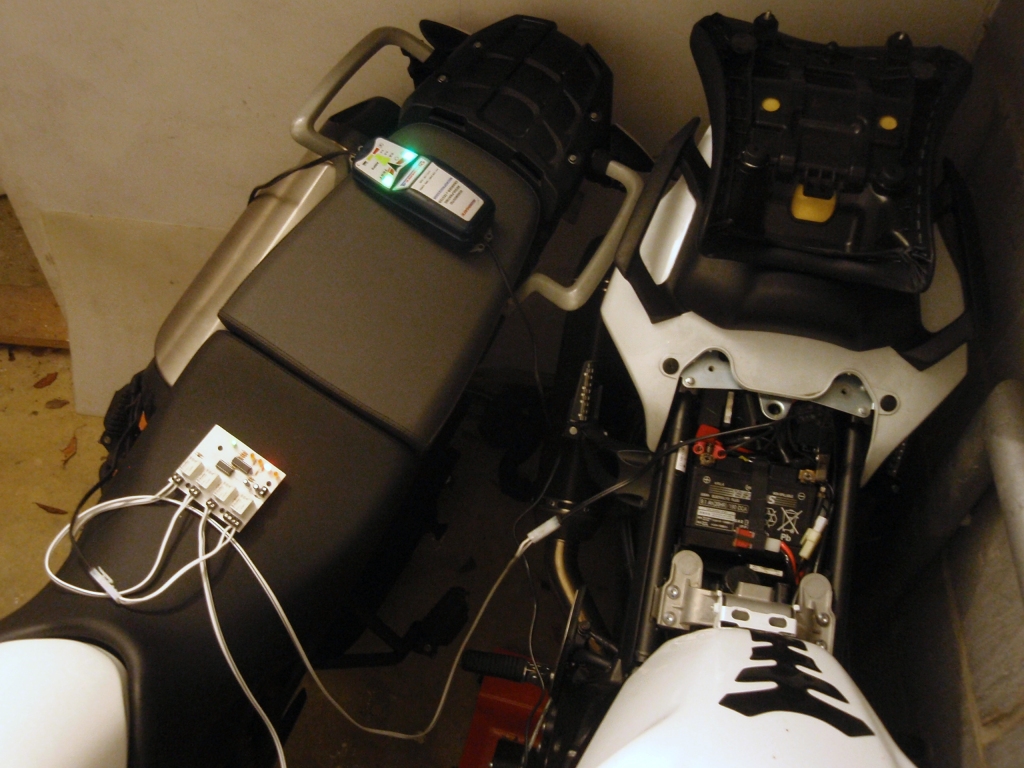
The circuit is powered using
the batteries on the connected motorbikes. Diodes D1 to
D4 feed power from each bikes battery to the circuit. The
diodes isolate the bikes batteries from each other and only the bike with
the highest battery terminal voltage actually powers the circuit; this
will normally be the battery currently charging.
The voltage at each of the
four outputs is fed to the microcontroller sense inputs via a
resistor network comprising 10K and 3K3 resistors. This
divides the input voltage by 4.03 so a voltage above
approximately 8 volts at the output will feed 2 volts to the
sense input of the microcontroller IC2. This is seen as a high logic level
by the software and
allows the controller to detect which outputs are actually
connected to a bike.
The 12 volt supply from the
bike battery feeds the relay coils and also to a 5
volt regulator IC1. This regulator IC is an LP2950 micro-power
precision Low Dropout regulator and provides regulated 5 volts to the
microcontroller. The relay coil voltage is a nominal 12V
DC but is rated to 1.5x this which is 18 volts so they are okay
working with typical battery terminal voltages of 12.5 to 14.8
volts.
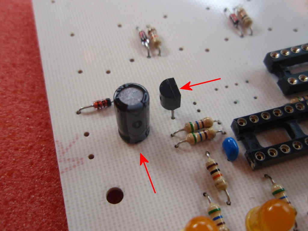
Capacitor C3 provides
decoupling of the input power. C2 does the same for the 5 volt
output. C4 is required by the voltage regulator IC1 to
maintain a stable output. Capacitor C3 is rated at 25
volts, don't use a lower voltage rated part here.
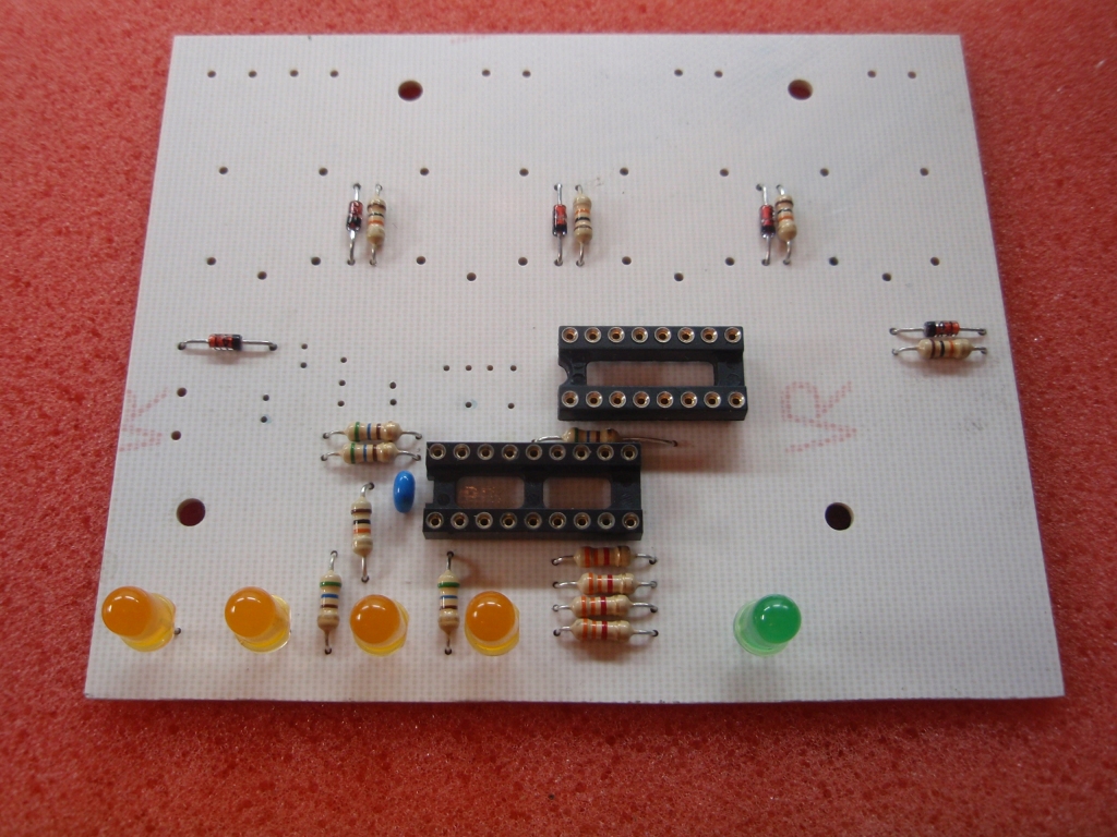
The five LEDs connect via 560
ohm resistors to the microcontroller. This is quite a high
value but it keeps the LED current around 5mA which helps keep
the overall current consumption of the circuit low.
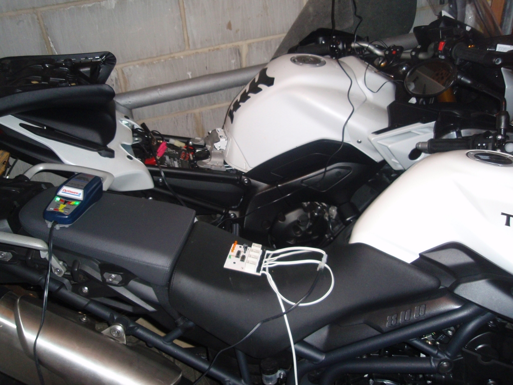
The ground connection of the
battery charger and all the bikes are connected together on the
PCB. The positive output from the charger is fed to
the common pole of all four relays. The output of each relay feeds one bike.
When the corresponding relay is turned on, the positive output
from the battery charger is connected to the bike and therefore allows
the battery to be charged.
A ULN2003A
Darlington transistor array is used to switch the relays using
four of the seven outputs. Each output of the
ULN2003A incorporates
a diode to provide clamping of the relay coil flyback voltage.
The choice of this IC over discrete components was made to keep
the PCB layout simpler and more compact.
Charging Current and Voltage
Quick digression here.
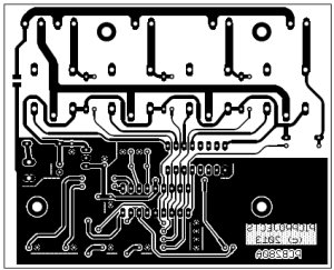
Although the relays are rated for 10 amp switching, the PCB
traces are only good for about 3 amps. This is more than
adequate for most motorbike chargers, in fact the charger I use only
outputs 800mA. If you heavily tin the PCB tracks with
solder around the relays and terminal blocks you can increase
this to maybe 6 amps. The circuit is designed to work with 12
volt batteries only - it won't work with 6 or 24 volt automotive
electrics.
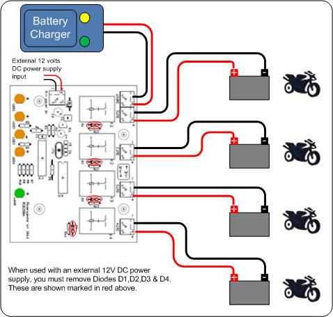
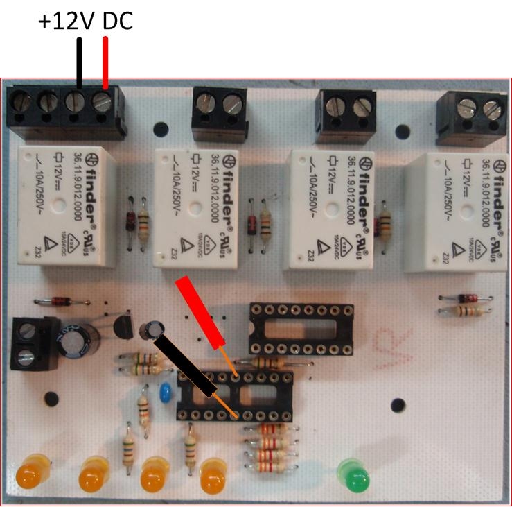
Power Supply
The board requires a nominal 12 volt
DC supply to operate. With D1-D4 installed the board is
powered from the batteries of the motorbikes attached to the
outputs. The battery with the highest voltage at its
terminals will forward bias one of the diodes, causing it to
conduct and power the controller. The other diodes are
then reverse biased and do not conduct. Typically the bike
under charge will have a higher battery terminal voltage than
the others so the controller doesn't drain the batteries
of the non-charging bikes.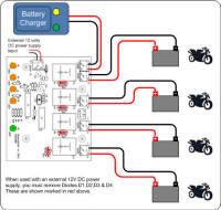
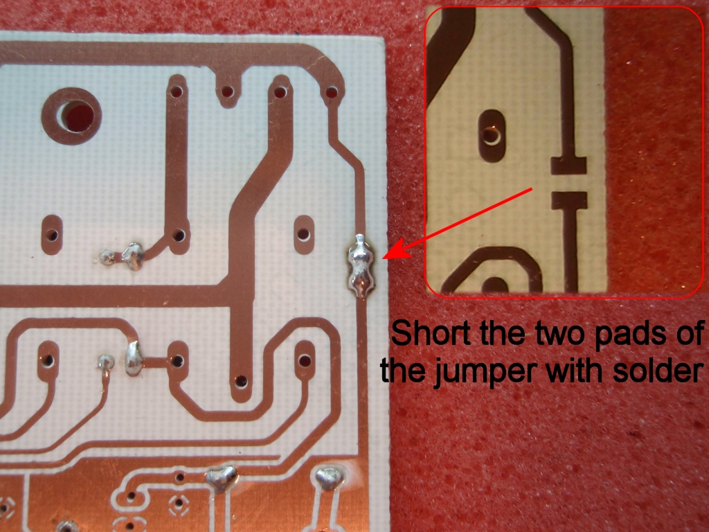
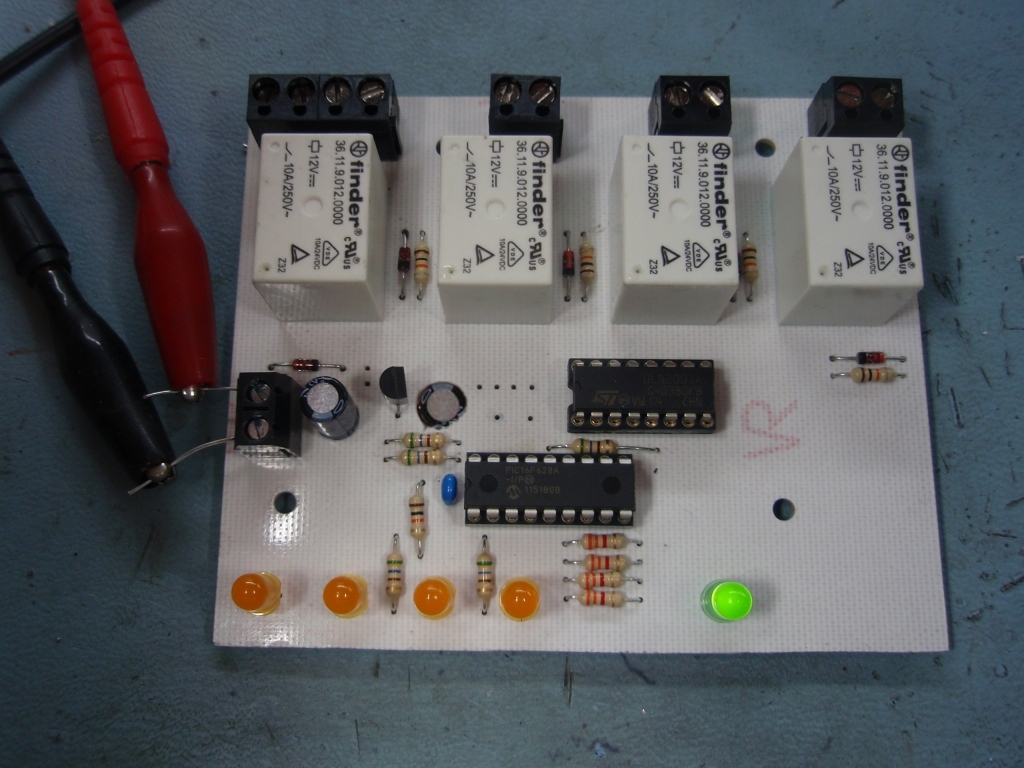
If you don't want it to work
this way you can use an external 12 volt DC power supply
connected to the 'external power input' connector. If you
do this you MUST omit diodes D1-D4. Also ensure the
power supply output does not have a connection to the AC mains
earth.
When using the external power
input terminal the board is protected from a reverse polarity connection by
diode D5.
Each relay requires about 35mA
to operate, the 5 LEDs when all on add another 25mA and the rest
of the circuit uses about 5mA. The heartbeat LED flashes
at 1Hz, and the channel connection LEDs for 100mS every 2.5
seconds, only the active channel LED is on constantly and since
only one relay is active at any time the average current
consumption is typically under 50mA.
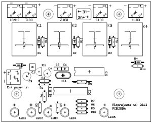
Building for less than four
channels
If you don't need four channels
you can omit the LEDs, resistors, relay and diode for an unused
channel. Even if a channel output isn't used you should
fit the 3K3 resistor (R7 through R10) to ensure the
channel sense input is held low and the software treats it as
unused.
External Crystal
The PCB is laid out to allow
the use of an external crystal for the microcontroller's clock
oscillator using XT1/C5/C6. I chose not to use an external
clock and instead use the internal RC oscillator. While
this doesn't give such accurate time delays, for the intended
application 10 minutes error in 12 hours isn't significant.
If you want to use a crystal it needs to be 4Mhz, the load
capacitors should be 15pF and you will need to change the
configuration word when programming the PIC to use external XT
crystal on RA6/RA7 for the clock source.
You can buy all the parts
needed to build this project from most component suppliers world
wide. In the UK you can get everything from Rapid Online and
I've included a parts list with their part numbers below.

All
Rapid parts/descriptions correct at 10 February 2013. You should
check part# and descriptions are correct when ordering in case
I've made a mistake transferring them onto this page.
|
Component |
Description |
Part # |
| R1-5 |
PACK 100 560R 0.25W CF
RESISTOR (Order 1 pack only) |
62-0364 |
| R6,R11-R14 |
PACK 100 10K 0.25W CF
RESISTOR (Order 1 pack only) |
62-0394 |
| R7-R10 |
PACK 100 3K3 0.25W CF
RESISTOR (Order 1 pack only) |
62-0382 |
| C2 |
100N 2.5MM X7R Dielect
Ceramic Capacitor |
11-3442 |
| C3 |
100uF 25 v low imp
Electrolytic capacitor |
11-2922 |
| C4 |
47uF 10v 5mm Micromin
Electro Capacitor |
11-1502 |
| IC1* |
LP2950CZ-5 micropower
regulator |
82-0680 |
| IC2** |
PIC12F628A-I/P |
73-3340 |
| IC3 |
ULN2003A |
82-0618 |
| D1-D5 |
1N4148 75V 200mA
signal diode |
47-3309 |
| LED1-4 |
Kingbright L-53LYD 5mm
Low Current Yellow Diffused LED 2mcd |
55-0856 |
| LED5 |
Kingbright L-53LGD 5mm
Low Current Green Diffused LED 2mcd |
55-0852 |
| |
|
|
| socket for IC2 |
18 Pin 0.3in Turned Pin
Socket |
22-1723 |
| socket for IC3 |
16 Pin 0.3in Turned Pin
Socket |
22-1722 |
| |
|
|
| K1-K4 |
Finder 12V Relay
(Miniature) SPDT 10A 36.11 |
60-4192 |
Terminal block
Qty 6 |
2 Way 16A Black
Interlocking Terminal Block (order 3) |
21-0440 |
Parts List Notes
All the resistors are
supplied in packs of 100
*
If you
can't get hold of the LP2950 you can substitute a 78L05 5-volt
regulator
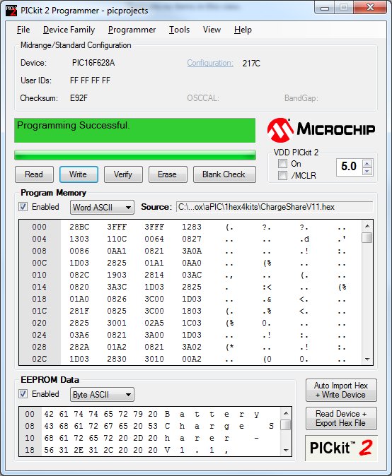
**
PIC16F628A
will need to be programmed with the HEX file available to
download at the bottom of this web page.
C1 is not used.
C5/C6/XT1 are optional components and not used in this design
 connect to the bikes but this needs me
to manually swap it from one bike to the next and between
forgetting to do it and not remembering which bike it was last
connected to it's all a bit unreliable.
connect to the bikes but this needs me
to manually swap it from one bike to the next and between
forgetting to do it and not remembering which bike it was last
connected to it's all a bit unreliable.