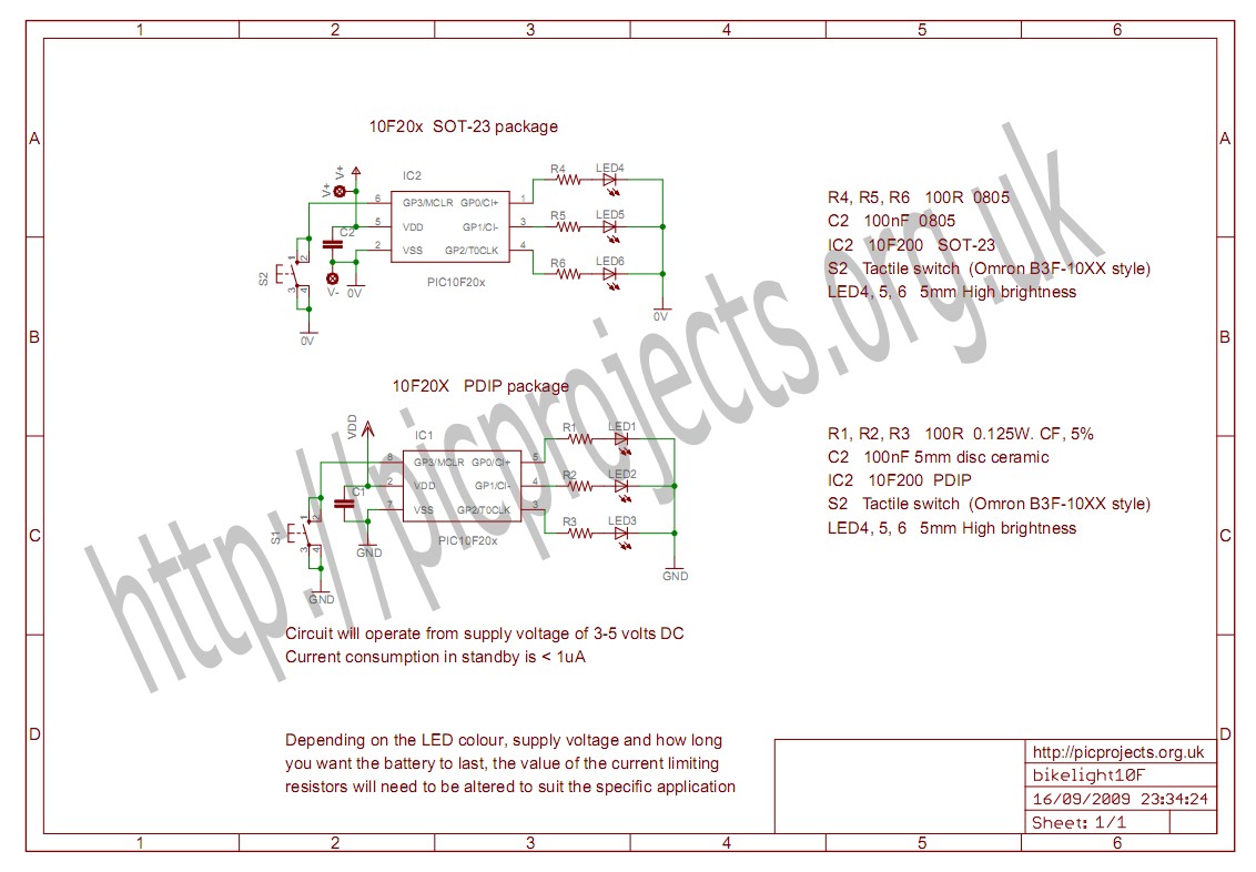
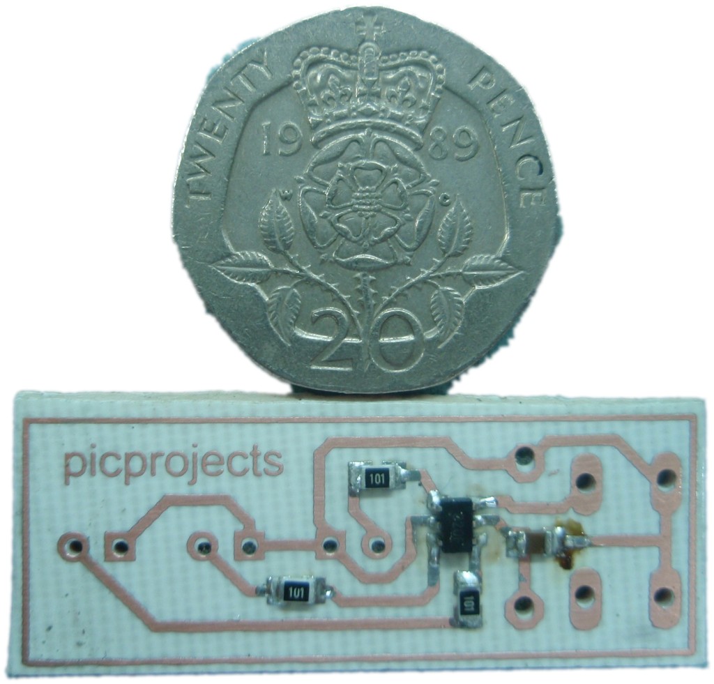
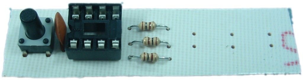
There are two functionally
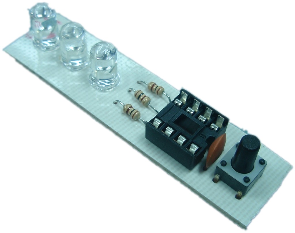
identical versions of the project presented on this page; a
small easy to assemble version using the 8-pin PDIP version of
the PIC10F20x and a very small version based on the SOT23
package PIC and surface mount components.
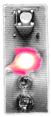
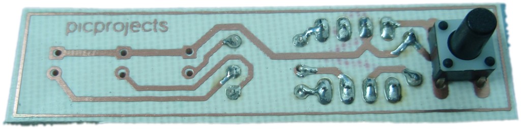
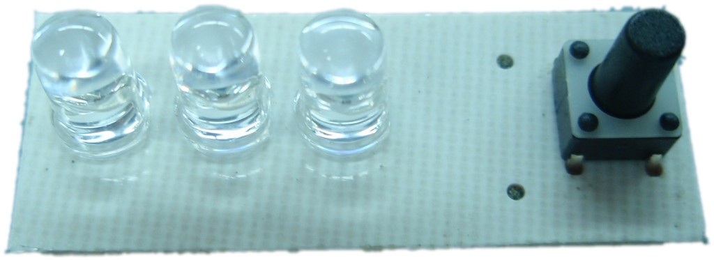
The circuit drives 3 LEDs from the I/O pins of the PIC microcontroller. A
single push button switch provides standby/power-on function as
well as mode selection.
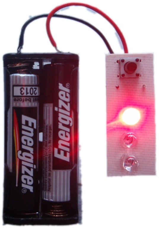
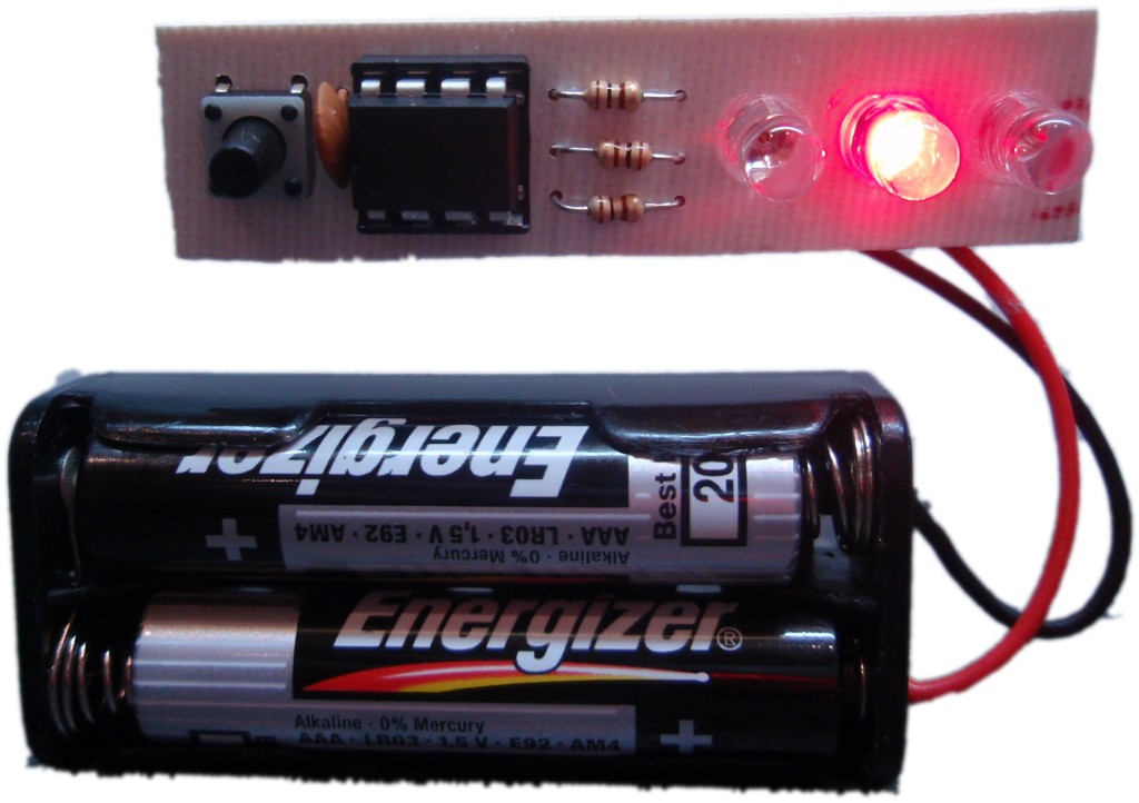
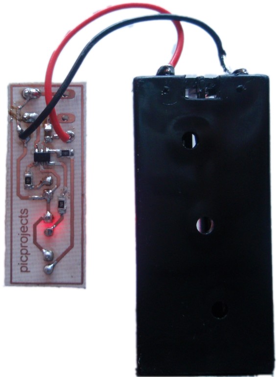
The circuit can operate from a
voltage in the range 2 to 5 volts although you will need to take
into account the forward voltage drop of the LEDs used; red LEDs
typically need at least 2 volts, white LEDs 3 volts. Current consumption in
operation depends on the LEDs used and the choice of current
limiting resistors. Typically it will be in the range of
10 to 30mA. In standby current consumption drops to less
than 1µA making it well suited to battery operation. The
100nF capacitor is used for decoupling of the power supply to
the PIC.
The LED functions are
defined by a lookup table in the PIC's program firmware.
If you have access to a PIC programmer and want to edit or
modify these you can download the source code (see bottom of this page).
The default modes supplied are:
- All LEDs constant on -
power save mode
- All LEDs constant on -
full brightness mode
- All LEDs blink at 2.5Hz -
power save mode
- Single LED walking
- All LEDs strobe mode 40mS
on / 600mS off
- All LEDs short flash, long
hold
- All LEDs burst strobe mode
6 x 20ms on / 60mS off followed by 1 second off.
To reduce power consumption the
firmware can drive each LED sequentially at very high speed so
only one LED is on at a time; because it does this around 1300 times
per second persistence of vision makes all the LEDs appear to be on
at the same time. This
reduces power consumption to that of a single LED, increasing
battery life. This feature can be selectively disabled,
providing slightly higher brightness at the expense of increased power
consumption when all LEDs are on. The operating mode is
defined in the mode sequence data table so if you're creating your
own sequences you can pick and choose how this feature is used.
LED / current limit resistor
calculation
To calculate the resistor needed
for a particular LED/ current requirement check out the website
below.
http://led.linear1.org/1led.wiz
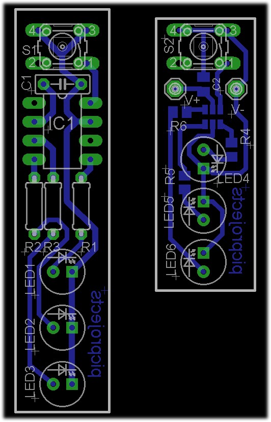
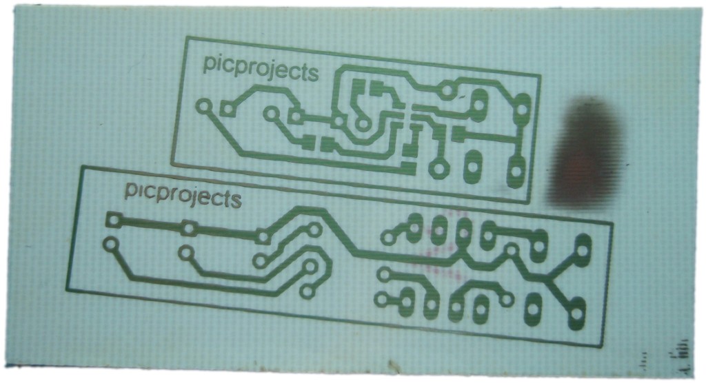
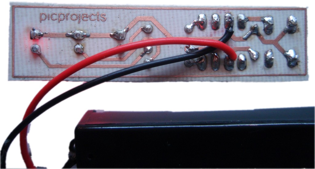
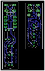
There are two sets of artwork
provided for the bike light.
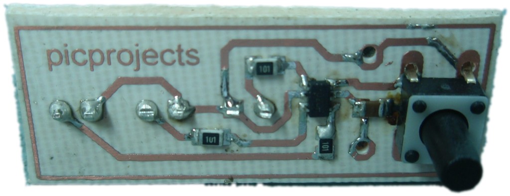
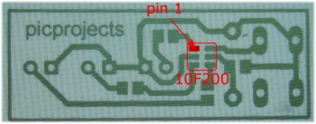
a) Through hole design for the
PDIP version of the 10F20x
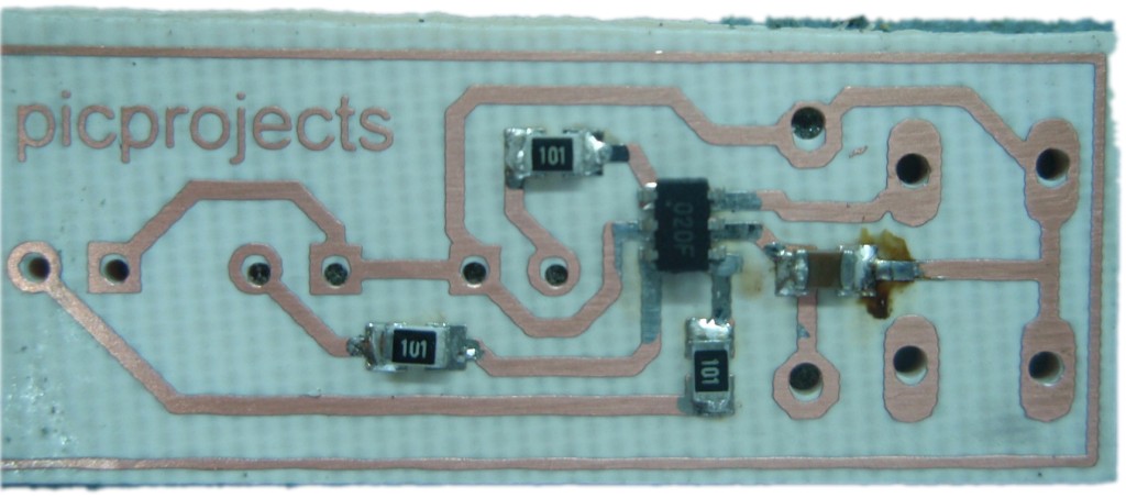
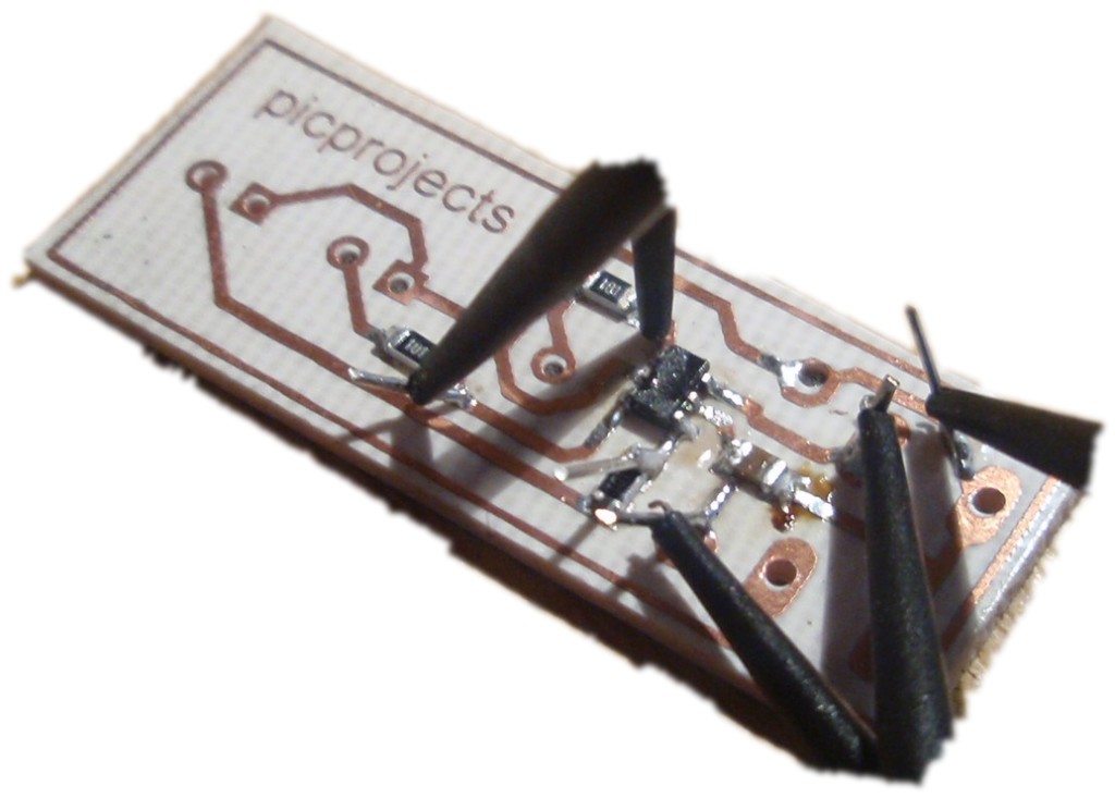
b) Part-surface mount design for the SOT-23 version of the
10F20x
 |
 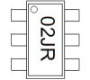
The
SOT-23 package has a small laser etched dot in the
corner nearest pin 1. You'll need
exceptional eyesight or a good bench magnifier to see
it. |
Download PCB
artwork in PDF

The artwork here is just a
starting point. You can design alternative layouts,
assemble it onto strip-board, or even take an existing bike
light and hack it to use the PIC from this project to control
it.
The HEX file is ready to
program straight into the PIC 10F200. The asm file is the
source code which you can modify or just view to see how it
works.
See the
Programmed
PICs section in the Picprojects
On-line store
now.
|
Description |
Filename |
Download link |
| Source
code for 10F200 / 10F202 |
bikelightv2.asm |
 download
 |
HEX file
ready to program into the PIC
for use with 10F200 only |
bikelightv2.HEX V1.0.0 17/09/2009 |
download
Checksum 402B |
If you need a PIC Programmer I
strongly recommend the
Microchip PICKit 2,
this is available from suppliers world wide or direct from
Microchip. It's reasonably cheap to buy and reliable.